6. Control Functions and Parameter Settings
6-1
Chapter 6 Control Functions and Parameter Settings
6-1 Monitor parameters
6-1 Monitor parameters
The monitor mode sequentially displays the frequency, power supply, etc., parameters recognised by the
VAT2000.
The symbols used in the “Application” column are:
ST : Indicates parameters used for all control modes (C30-0 = 1 to 5) including V/f control (constant
torque, variable torque), sensor-less vector control, and vector control with sensor and PM motor
control.
V/f : Indicates parameters used for V/f control (constant torque, variable torque) (C30-0 = 1, 2).
VEC : Indicates parameters used for IM sensor-less vector control and IM vector control with sensor
(C30-0 = 3, 4).
PM : Indicates parameters that are used for PM motor control (C30-0=5)
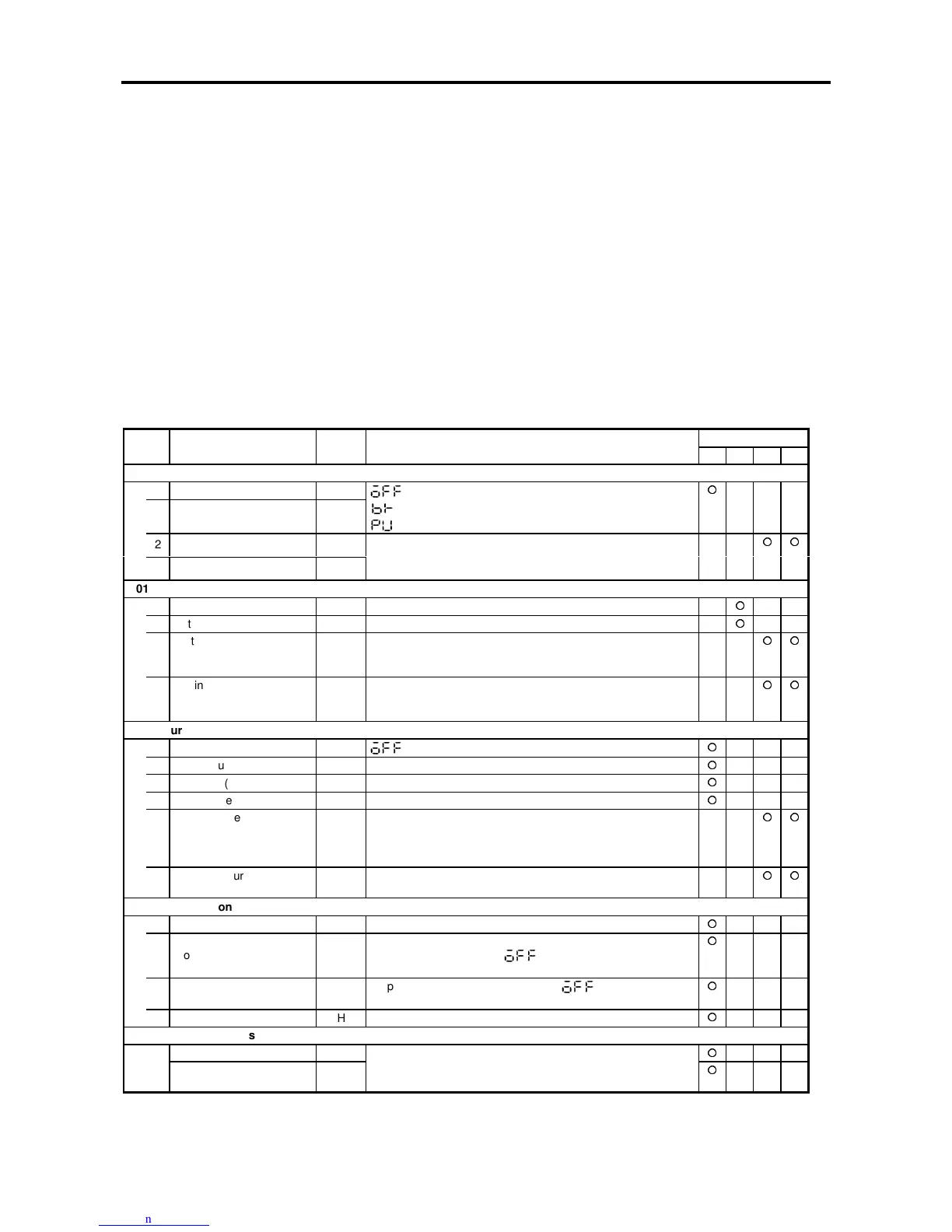
Monitor parameters list
ApplicationNo. Parameter Unit Remarks
ST V/f VEC PM
D00 – Output frequency monitor
0 Output frequency in Hz Hz
1 Output frequency in % %
will display when the VAT2000 is in standby.
displays while the DC brake is in action.
is displayed during pick up (Flying Start).
2 Motor speed in min
–1
min
–1
3 Motor speed in % %
The forward run direction is displayed with the + polarity, and
the reverse run direction with the – polarity. (This is displayed
even when stopped.)
D01 – Frequency setting monitor
0 Setting frequency in Hz Hz The currently selected frequency setting value is displayed.
1 Setting frequency in % % The max. frequency is displayed as 100%.
3 Setting speed
(Output Ramp)
min
–1
The set speed at ASR input point is displayed.
The forward run direction is displayed with the + polarity, and
the reverse run direction with the – polarity.
4 Setting speed
(Input Ramp)
min
–1
The set speed at the ramp function’s input point is displayed.
The forward run direction is displayed with the + polarity, and
the reverse run direction with the – polarity.
D02 – Current monitor
0 Output current Amps A will display when the VAT2000 is in standby.
1 Output current in % % The motor rated current is displayed as 100%.
2 Overload (OLT) monitor % OLT functions when this value reaches 100%.
3 Heatsink temperature °C
4 Torque current detection % The torque current detection value is displayed using the
motor rated current as 100%. The forward run direction torque
is displayed with the + polarity, and the reverse run direction
torque with the – polarity.
5 Excitation current
detection
% The excitation current value is displayed using the motor rated
current as 100%.
D03 – Voltage monitor
0 DC voltage V Displays the voltage of the DC link circuit in the main circuit.
1
Output voltage
(command)
V
Displays output voltage command. The display may differ from
the actual output voltage.
will display when the drive is
in standby.
2 Output power kW Displays the inverter’s output power. will display when
the drive is in standby.
3 Carrier frequency kHz The current carrier frequency is displayed.
D04 – Sequence status
0 ~ 2 Input
3 ~ 4 Output
The ON/OFF state of the internal sequence data will display.
The correspondence of each LED segment and signal is
shown in the next page.

 Loading...


