Home
Hypertherm
Welding System
XPR300
Hypertherm XPR300 User Manual
4
of 1
of 1 rating
438 pages
Give review
Manual
Specs
To Next Page
To Next Page
To Previous Page
To Previous Page
Loading...
Connect for Communication
4
17
2
8094
80
In
st
ru
ct
ion
Man
ua
l
XPR30
0
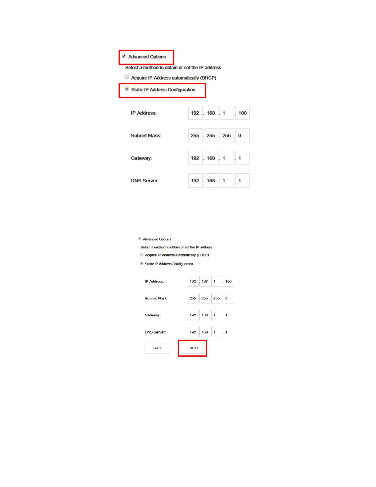
b.
St
atic I
P (advanced users only.)
4.
Choose
Next
to go to the W
ireless Configuration Sum
mary screen.
Thi
s page shows information about the
SSID
,
Channel
, and
Security
type.
171
173
Table of Contents
Table of Contents
9
List of Tables
21
Electromagnetic Compatibility (EMC
23
Introduction
23
Installation and Use
23
Assessment of Area
23
Methods of Reducing Emissions
23
Mains Supply
23
Maintenance of Cutting Equipment
23
Cutting Cables
23
Equipotential Bonding
23
Earthing of the Workpiece
24
Screening and Shielding
24
Warranty
25
Attention
25
General
25
Patent Indemnity
25
Limitation of Liability
25
National and Local Codes
25
Liability Cap
26
Insurance
26
Transfer of Rights
26
Parts Coverage
26
Product
26
Waterjet Product Warranty Coverage
26
Specifications
27
Terminology
27
XPR Cutting System Description
28
Gas Connect Consoles
28
General
28
Plasma Power Supply
28
Torch
28
Torchconnect Console
28
Plasma Power Supply (Part Number Varies)
29
Table 1 - Plasma Power Supply General Specifications
30
Table 2 - Plasma Power Supply Part Numbers and Specifications
31
Gas Connect Console (Part Number Varies)
32
Table 3 - Gas Connect Console Part Numbers and Dimensions
32
Torchconnect Console (078618)
33
Table 4 - Length and Weight by Sleeve Type
34
Table 5 - General Torch Specifications
34
Torch (Part Number Varies)
34
Critical Raw Materials
35
Safety and EMC Symbols and Marks
36
Symbols and Marks
36
IEC Symbols
37
Qualifications and Requirements
39
Document Requirements
39
Operator Qualifications
40
Qualifications of Service Personnel
41
System Electrical Requirements
42
Code Conformity
42
General Input Power Requirements
42
Input Power Requirements
42
Line-Disconnect Switch Requirements
43
Plasma Power Supply
43
Table 6 - Input Power Requirements
43
Circuit Breaker and Fuse Requirements
44
Main Power Cord Requirements
44
Input Power Requirements for CE Units
45
Remote On-Off Switch
45
Process Gas Requirements (Core, VWI, and Optimix Gas Connect Consoles)
46
Table 7 - Gas Quality, Pressure, and Flow Requirements
46
Code Conformity
47
Plumbing for Supply Gases
47
Table 8 - Recommended Sizes for Gas Fittings
48
Regulators for Supply Gases
49
Shield Water Requirements (VWI and Optimix)
51
Table 10 - Purity Requirements for Shield Water
51
Table 9 - Quality, Pressure, and Flow Requirements for Shield Water
51
Additional Regulator Requirement for Shield Water (Optional)
52
Plumbing and Hose Requirements for Shield Water
52
Table 11 - Torque Specifications
52
Torque Requirements for Gas or Water Plumbing and Hose Connections
52
Requirements for Shield Water Removal for Freezing-Ambient Temperatures
53
Coolant Requirements
54
Coolant Requirements for Operation between -10°C - 40°C (14°F - 104°F)
55
Coolant Requirements for Operation in Temperatures above 40°C (104°F)
55
Flow Requirements for Coolant
56
Purity Requirements for Coolant Water
56
Table 12 - Purity Measurement Methods for Coolant Water
56
Requirements to Position System Components
57
Recommended Configuration with the Core Gas Connect Console
58
Recommended Configuration with the VWI or Optimix Gas Connect Console
59
Length Requirements for Hoses, Cables, and Leads
60
Site Requirements
60
Table 13 - Recommendations for Where to Position System Components
60
Table 14 - Length Ranges for Interconnect Hoses, Cables, and Leads
60
Bend Radius Requirements for Hoses, Cables, and Leads
61
Maximum Diameters for Console-To-Console Lead Sets
61
Distance Requirements between High-Frequency Leads and Control Cables
62
Distance Requirements for Ventilation and Access
62
Distance Requirements for Communications
63
Table 15 - Maximum Distance between the Plasma Power Supply and Controlling Device
63
Wireless Compliance
63
Torch Lifter Requirements
64
Torch Mounting Bracket Requirements
64
Adjustable Settings
65
CNC Requirements
65
Display Settings
65
Remote On-Off Switch
65
Diagnostics and Troubleshooting
66
Introduction
67
Recommended Grounding and Shielding
67
Types of Grounding
67
Grounding Practices
68
Example Grounding Diagram with an XPR Cutting System
71
Installation
73
Before You Begin
73
Installation Checklist
74
System Requirements
74
Installation Steps
77
Safety Instructions Related to Installation
79
Configuration with Core Gas Connect Console
82
Configuration with VWI or Optimix Gas Connect Console
83
Installation Steps
84
Plasma Power Supply
84
Position the System Components
84
Table 16 - Equipment to Lift or Move the Plasma Power Supply
84
Gas Connect Console
85
Torchconnect Console
87
Ground the System Components
90
Remove the External Panels from the System Components
92
CAN Cable
96
Coolant Hose Set
96
Negative Lead with Strain Relief
96
Pilot Arc Lead with Strain Relief
96
Power Cable
96
Prepare the Hoses, Cables, and Leads
96
Work Lead
96
Pilot Arc and Coolant Hose Set Assembly
97
Pilot Arc, Coolant Hose Set, and Shield Water Assembly (Only for VWI and Optimix)
97
Power, CAN, 3-Gas Assembly (Only for Core)
97
Power, CAN, and 5-Gas Assembly (Only for VWI and Optimix)
97
Air Hose (Black)
98
Argon (VWI or Optimix Only) (Black)
98
F5 (VWI or Optimix Only) (Red)
98
Hydrogen (Optimix Only) (Red)
98
Nitrogen Hose (Black)
98
Oxygen Hose (Blue)
98
Shield Water (VWI or Optimix Only) (Blue)
98
Connect the Plasma Power Supply and Gas Connect Console (Core, VWI, or Optimix)
99
Table 17 - Definitions of Symbols on the Label Inside the Plasma Power Supply
99
Connect the Coolant Hose Set
100
Connect the Power Cable
102
Connect the CAN Cable
103
Connect the Work Lead to the Plasma Power Supply and Cutting Table
104
Connect the Negative Lead with Strain Relief
105
Connect the Pilot Arc Lead with Strain Relief
107
Connect the Gas Connect Console (Core) to the Torchconnect Console
109
Connect the Pilot Arc and Coolant Hose Set Assembly (Core)
109
Connect the Power, CAN, and 3-Gas Assembly (Core)
112
Connect the Gas Connect Console (VWI or Optimix) to the Torchconnect Console
113
Connect the Pilot Arc, Coolant Hose Set, and Shield Water Assembly (VWI or Optimix)
113
Connect the Power, CAN, and 5-Gas Assembly (VWI or Optimix)
116
Install and Connect the Supply Gases
117
Install Gas Regulators
118
Table 18 - Torque Specifications
118
Table 19 - Torque Specifications
118
Connect Supply Gases to the Gas Connect Console (Core)
119
Table 20 - Recommended Sizes for Gas Fittings
121
Connect Supply Gases and Shield Water to the Gas Connect Console (VWI or Optimix)
122
Connect the Supply Gases
124
Table 21 - Recommended Sizes for Gas Fittings
124
Connect Optional Shield Water to the Gas Connect Console (VWI or Optimix)
126
Connect the Torch Receptacle to the Torchconnect Console
126
Install the Torch in the Torch Mounting Bracket
131
Install the Consumables
133
Install the Torch into the Torch Receptacle
135
Connect Electric Power to the Cutting System
136
Table 22 - Color Codes for Main Power Cord Wires
137
Example Configurations for Consumables
138
Ferrous (Mild Steel) Example Configurations
138
Mild Steel - 50 a - O /Air
138
Mild Steel - 80 A, 130 A, 170 A, 220 A, and 300 a - O /Air
139
Non-Ferrous (Stainless Steel and Aluminum) Example Configurations
140
Non-Ferrous - 40 a - N and Air/Air
140
Non-Ferrouson-Ferrous - 60 a - F5/Non-Ferrous 2 **, Non-Ferrous
141
Non-Ferrouson-Ferrous - 80 a - F5/Non-Ferrous 2 **, Non-Ferrous
142
Ar-N
143
Non-Ferrous - 130 a - N
143
Ar-N
144
Non-Ferrous - 170 a - N
144
Ar-N
145
N , /H /N **, N //H /N , /H /N **, N //H O***
145
Non-Ferrous - 300 a - N
145
Connect for Communication
147
Table 23 - Communication Requirements and Options
148
How to Connect to the Plasma Power Supply with Ethercat
149
How to Connect to the Plasma Power Supply with Serial RS-422
151
Table 24 - Pinout for Serial RS-422 Interface Cable
152
How to Connect to the Plasma Power Supply with Discrete
154
Table 25 - Pinout for J14 on the Discrete Cable
155
Table 26 - Pinout for J19 on the Discrete Cable
156
VDC3 Board Installation (for AVC with RS-422 and Discrete-Only)
158
Diagram of Board, Cable, and Wire Connections
159
How to Install the VDC3 Board (141511)
160
How to Connect the VDC3 Board (141511)
163
Table 27 - Pinout for J2 on the VDC3 Board
165
How to Connect to the Plasma Power Supply with the XPR Web Interface
166
Web Interface Support Information
166
Use AP Mode to Connect
167
Use Network Mode to Connect
169
Select an Existing Network
171
Set up Manually
174
Access the XPR Web Interface after Setup in Network Mode
177
Change the Limited AP Settings
178
Reset the Wireless Module
180
How to Disable the Wireless Connection
182
Web Interface Screen Information
184
Plasma Power Supply
185
Gas System
186
Log
189
Operate
190
Other
191
How to Change the Device that Has Control
192
How to Use Ohmic Contact Sense
193
Internal Ohmic Contact Sense
193
Ohmic Relay Overview
193
External Ohmic Contact Sense
194
How to Install a Remote On-Off Switch
196
Examples of Output Circuits
197
Examples of Input Circuits
198
Coolant Installation
199
Overview
199
How to Fill the Cutting System with Coolant
200
Operation
203
Overview
203
Controls and Indicators
204
Cnc
204
Controls
204
Wireless Device
204
Indicators
205
Power-Indicator Leds
205
CNC Display
206
Powerup State (1)
207
Sequence of Operation
207
States of Operation for the XPR Cutting System
207
Initial Checks State (2)
208
Gas Purge/Pump on State (3)
209
Preflow/Charge DC State (7)
210
Wait for Start State (5)
210
Ignite State (8)
211
Pilot Arc State (9)
212
Rampup State (11)
213
Steady State (12)
213
End of Cycle State (14)
214
High-Voltage Relay Stages (Closed or Opened) in the Ohmic Circuit
214
Rampdown State (13)
214
Automatic Purges
215
Gas-Change Purges for Optimix or VWI XPR Cutting Systems
215
Process-Setup Purges for All XPR Cutting Systems
216
How to Choose the Torch Positions and Process Settings You Need
217
Cutting
217
Marking
217
Perpendicular-Position Cutting, Marking, and Piercing
217
Piercing
217
Bevel Cutting
218
Bevel Compensation Tables
219
Ferrous (Mild Steel) Processes
219
Non-Ferrous (Stainless Steel and Aluminum) Processes
220
Table 28 - Available Non-Ferrous Processes by Gas Connect Console Type and Gas Type
220
Table 29 - Process Recommendations for Cut Quality, Based on Metal Thickness and Type
220
Stainless Steel
221
Aluminum
222
Processes for Special Applications
223
Underwater Cutting
223
Mirror Cutting
224
Process Selection
225
How to Use Process Ids to Access Optimal Settings
225
Process ID Offsets / Overrides
226
How to Use Cut Charts
227
Process Categories
227
Process Core Thickness (PCT)
227
Table 30 - Process Category Options and Expected Quality-Speed Results for Ferrous (Mild Steel) Processes
228
Table 31 - Process Category Options and Expected Quality-Speed Results for Non-Ferrous Processes
229
How to Select Consumables
230
Factors of Cut Quality
230
Dross
230
How to Get the Results You Want
230
General Recommendations for All Processes
231
Recommendations for Perpendicular-Position Cutting Processes
231
Recommendations for Piercing Processes
232
Recommendations for Bevel-Cutting Processes
233
Recommendations for Marking Processes
233
Arc Response Technology
234
Automatic Torch Protection
234
How to Maximize the Life of Consumable Parts
234
Automatic Rampdown Error Protection
235
Maintenance
237
Overview
237
Table 32 - Inspection, Preventive Maintenance, and Cleaning Tasks
238
How to Do Daily Inspections
239
Remove the Power from the Cutting System
240
Examine the Connections and Fittings
241
Examine the Gas Regulators
241
Examine the Shield Water Regulator (if Applicable)
241
Examine the Consumable Parts, Torch, and Torch Receptacle
242
Remove the Torch and Consumable Parts
242
Examine the Consumable Parts
243
Table 33 - Inspection Tasks for Consumables
243
Examine the Torch
245
Examine the Torch Receptacle
246
Examine the Torch Lead
247
How to Replace the Water Tube
248
How to Identify Emitter Wear
249
How to Measure the Pit Depth of an Electrode
252
How to Do Coolant Maintenance
253
Estimate the Total Coolant Volume for Your Cutting System
254
Replace All of the Coolant
254
Remove Old Coolant from the Coolant System
255
Diagnostics and Troubleshooting
259
Overview
259
Safety Considerations
260
Initial Inspection Steps
261
Remove the Power from the Cutting System
261
Examine the Pcbs
263
Table 34 - PCB Names and Locations
264
Measure the Line Voltage between the Terminals Inside the Plasma Power Supply
265
Diagnostic Codes
267
How to Diagnose and Troubleshoot Diagnostic Codes
267
Table 35 - Diagnostic Codes in the Web Interface
268
CAN Codes
269
Table 36 - Diagnostic Codes
269
For CAN Cable and Jumper Block, 507 - 508 for CAN Network and Bus, 600 - 602 for no CAN Communication)
311
Low Shield Water Pressure Code (532)
317
Low Shield Gas Pressure Code (534)
318
Low Coolant Flow Codes (540 - 542)
319
High Coolant Flow Codes (543 - 544)
321
Table 37 - Minimum and Maximum Ohmic Resistance Values for Thermistors
324
Table 38 - Minimum and Maximum Ohmic Resistance Values for Thermistors
329
Table 39 - Minimum and Maximum Ohmic Resistance Values for Thermistors
346
Other manuals for Hypertherm XPR300
Replacement Part Procedures
162 pages
Preventive Maintenance Program
41 pages
4
Based on 1 rating
Ask a question
Give review
Questions and Answers:
Need help?
Do you have a question about the Hypertherm XPR300 and is the answer not in the manual?
Ask a question
Hypertherm XPR300 Specifications
General
Brand
Hypertherm
Model
XPR300
Category
Welding System
Language
English
Related product manuals
Hypertherm XPR170
438 pages
Hypertherm XPR Series
41 pages
Hypertherm Powermax45 XP
174 pages
Hypertherm Powermax30 XP
201 pages
Hypertherm MAXPRO200
105 pages
Hypertherm powermax65
150 pages
Hypertherm POWERMAX 45
93 pages
Hypertherm Powermax 30
88 pages
Hypertherm Powermax 65
248 pages
Hypertherm Powermax 85
248 pages
Hypertherm powermax1250
89 pages
Hypertherm Powermax 125
317 pages

 Loading...


