Diagnostics and Troubleshooting
264 809480 Instruction Manual XPR300
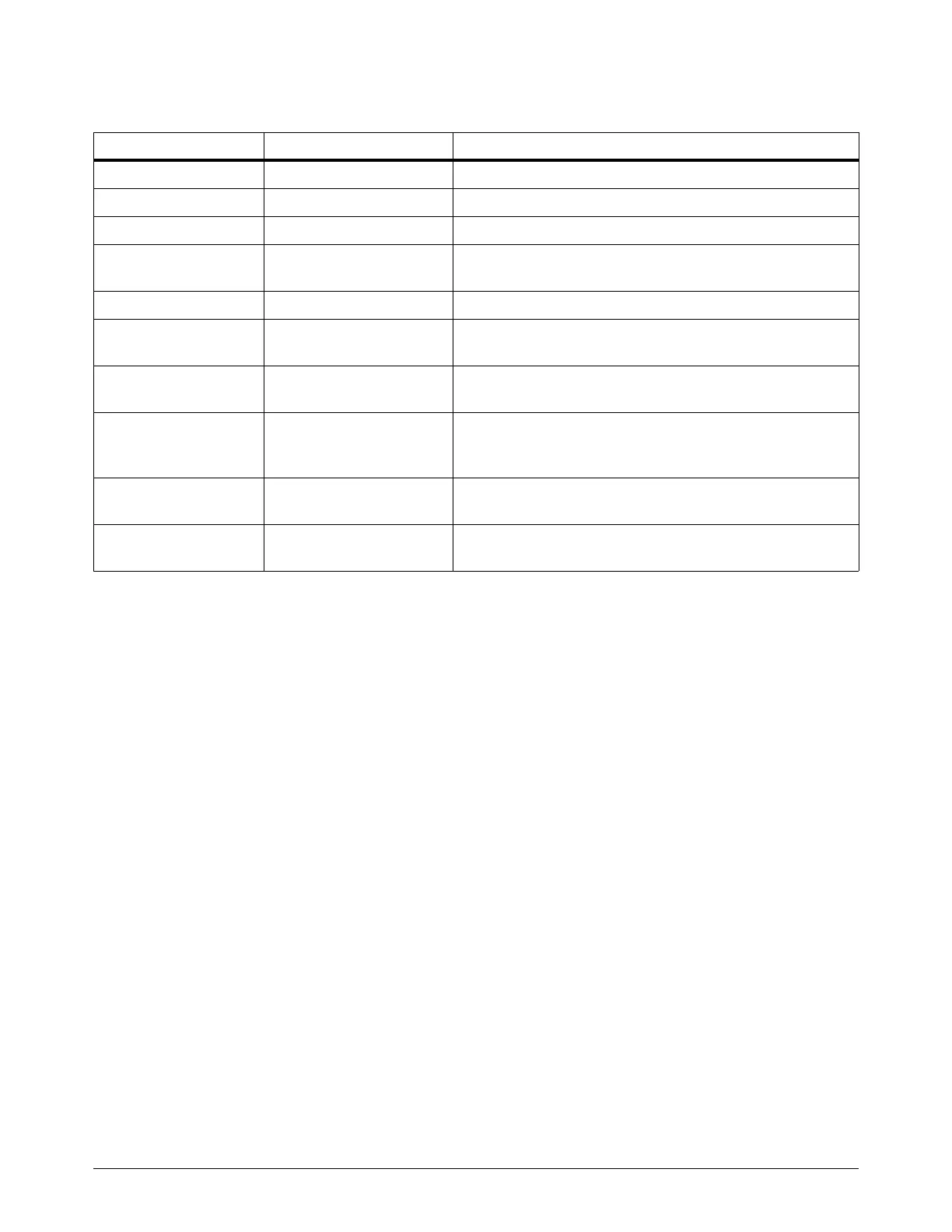
Table 34 – PCB names and locations
3. Examine the PCB. Look for:
Loose or disconnected PCB connectors
Loose or disconnected PCBs
Discoloration
Damage
4. If you find a PCB that is loose, reconnect it if possible.
5. If you find a PCB that has damage or discoloration, replace it.
See Parts List on page 361 for part numbers and reorder information.
6. If all PCBs are in good condition, measure the line voltage between the terminals inside of the
plasma power supply. Refer to Measure the line voltage between the terminals inside the plasma
power supply on page 265.
7. If you cannot find or resolve the problem with these corrective actions, contact your cutting
machine supplier or regional Hypertherm Technical Service team.
PCB name Location See the following drawings to PCB location page
Power distribution PCB Plasma power supply Refer to Control side – view 1 on page 369.
Control PCB Plasma power supply Refer to Control side – view 2 on page 370.
Chopper assembly PCB Plasma power supply Refer to Control side – view 2 on page 370.
Start-circuit assembly
PCB
Plasma power supply Refer to Control side – view 1 on page 369.
I/O PCB Plasma power supply Refer to Control side – view 2 on page 370.
Fan power distribution
PCB
Plasma power supply Refer to Fans on page 363.
Control PCB Gas connect console Refer to Gas connect console manifold side parts on
page 374.
High-frequency,
high-voltage ignition
PCB
Gas connect console Refer to Gas connect console high-voltage side parts on
page 373.
Ohmic contact PCB Torch connect console Refer to Torch connect console manifold side – view 1 on
page 383.
Control PCB Torch connect console Refer to Torch connect console manifold side – view 1 on
page 383.

 Loading...


