Qualifications and Requirements
XPR300 Instruction Manual 809480 71
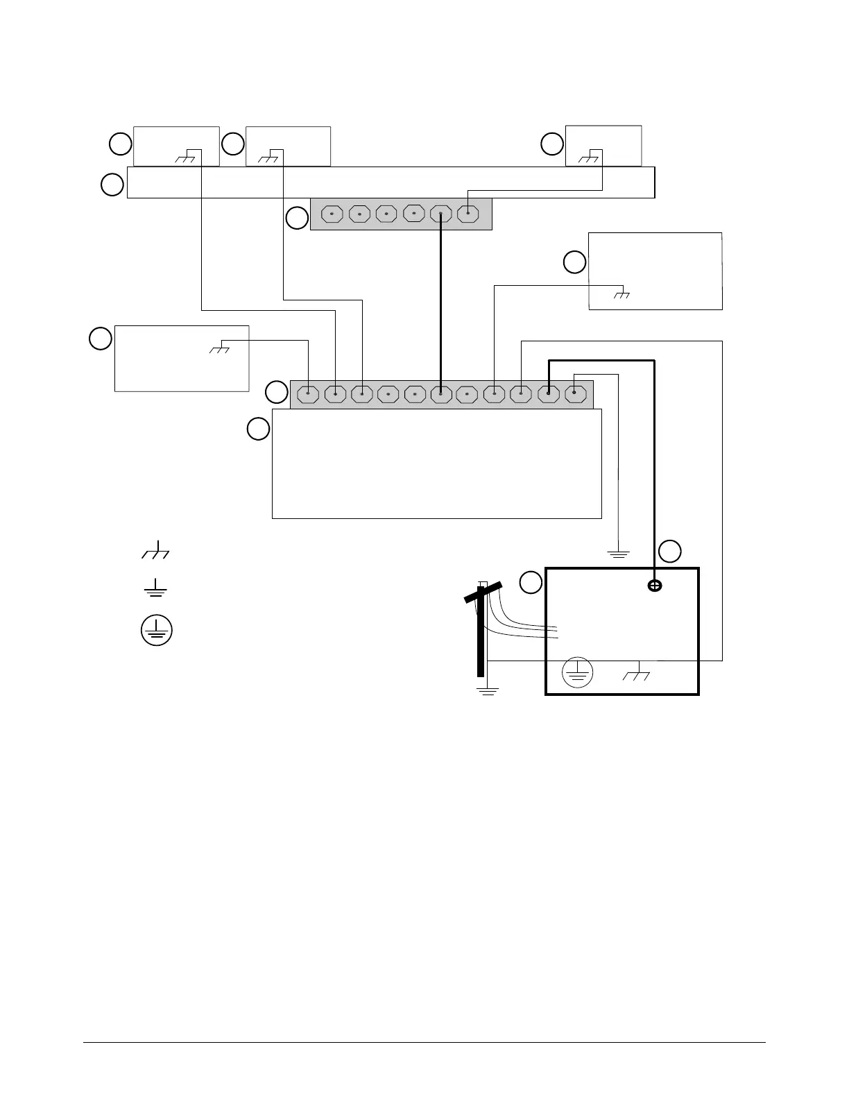
Example grounding diagram with an XPR cutting system
This example is based on practices in North America. Other regions can
have different local or national electrical codes. Hypertherm recommends
that you consult your local and national electrical codes to make sure that
the grounding and shielding practices that you use satisfy the
requirements for your location.
Chassis and EMI ground
Service ground
1
2
3
4
5
6
7
8
9
10
11
PE earth ground
1 Cutting table
2 Gantry
3 Plasma system
4 Table ground bus bar
5 Gantry ground bus bar
6 Torch height control lifter
7 Torch connect console
8 CNC controller
9 Torch height control module
10 Gas connect console. Connect to table ground
bus bar.*
11 DC power ground (work)
* The ignition console is integrated into the gas connect
console for XPR cutting systems.

 Loading...


