Diagnostics and Troubleshooting
XPR300 Instruction Manual 809480 329
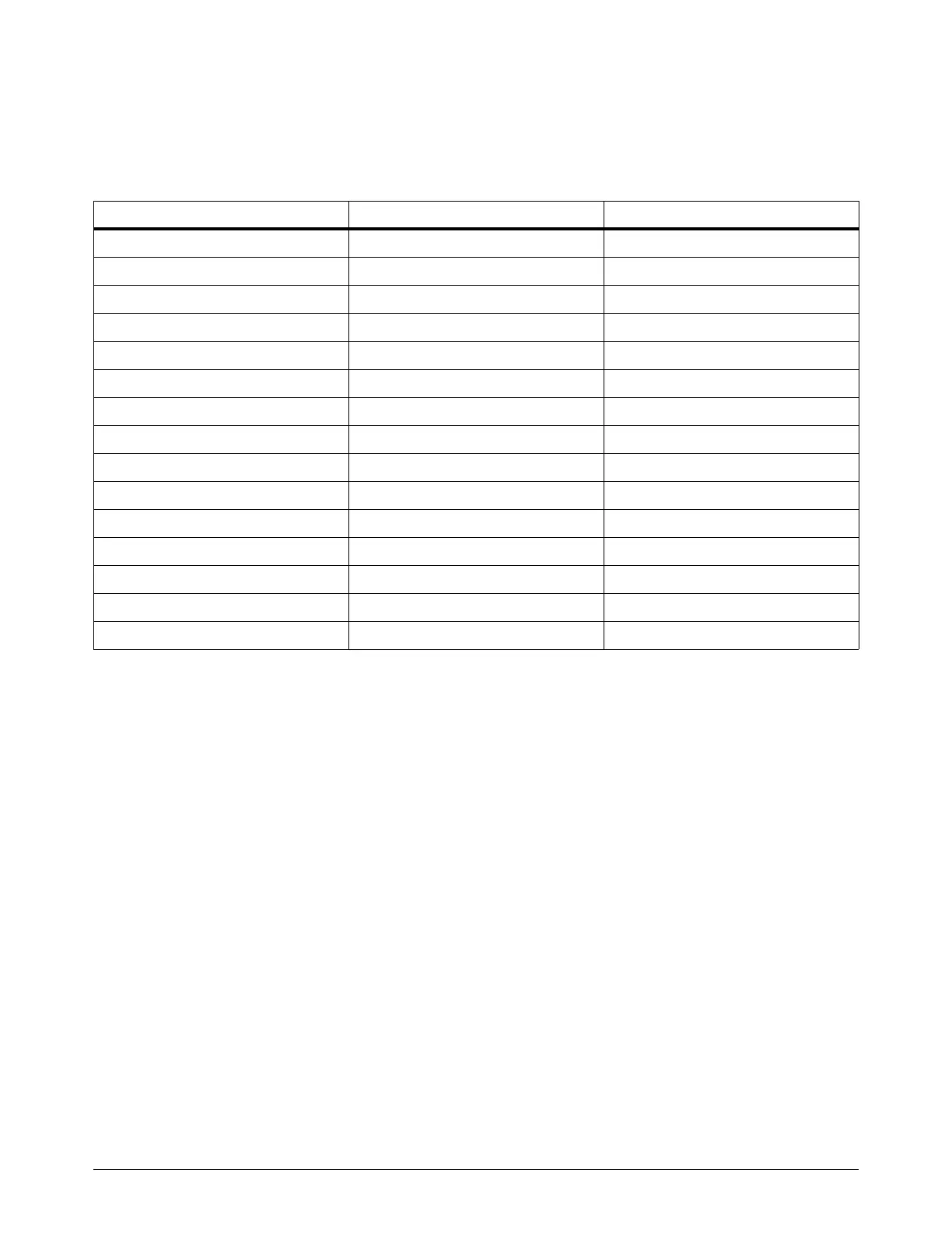
c. Look for a resistance value from each thermistor wire that is outside of the minimum or
maximum in Table 38:
Table 3 8 – Minimum and maximum ohmic resistance values for thermistors
At approximately 25ºC (77ºF), you can expect a resistance of
approximately 10,000 ohms.
d. If the ohmic resistance is outside of the minimum or maximum value in Table 38 on
page 329, contact your cutting machine supplier or regional Hypertherm Technical Service
team. They can help you to decide if there is a wiring fault or if thermistor replacement is
necessary.
e. If the resistance is at or very near 0 ohms:
Inspect the wiring between each thermistor and its connector pins.
Look for shorts between wires or to the ground.
9. If the thermistor resistance is within range when the thermistor is disconnected from the control
PCB and the code continues when the thermistor is reconnected to the control PCB, contact
your cutting machine supplier or regional Hypertherm Technical Service team. They can help you
decide if control PCB replacement is necessary. Refer to Plasma power supply control PCB
(141322) on page 351.
Thermistor temperature Minimum resistance (Ohms) Maximum resistance (Ohms)
25ºC (77ºF) 9,000 11,000
35ºC (95ºF) 5,000 7,000
45ºC (113ºF) 3,900 4,900
55ºC (131ºF) 2,500 3,500
65ºC (149ºF) 1,500 2,500
75ºC (167ºF) 1,000 2,000
85ºC (185ºF) 750 1,250
95ºC (203ºF) 600 1,000
105ºC (221ºF) 400 800
115ºC (239ºF) 300 600
125ºC (257ºF) 200 500
135ºC (275ºF) 150 400
145ºC (293ºF) 150 250
155ºC (311ºF) 125 225
165ºC (329ºF) 100 175

 Loading...


