Operation
XPR300 Instruction Manual 809480 207
Sequence of operation
The flowcharts on the following pages show the sequence of operation for the XPR cutting system.
States of operation for the XPR cutting system
Each state of operation is assigned a unique name and number for identification purposes. The type
of name you see (name or number) depends on your cutting system settings.
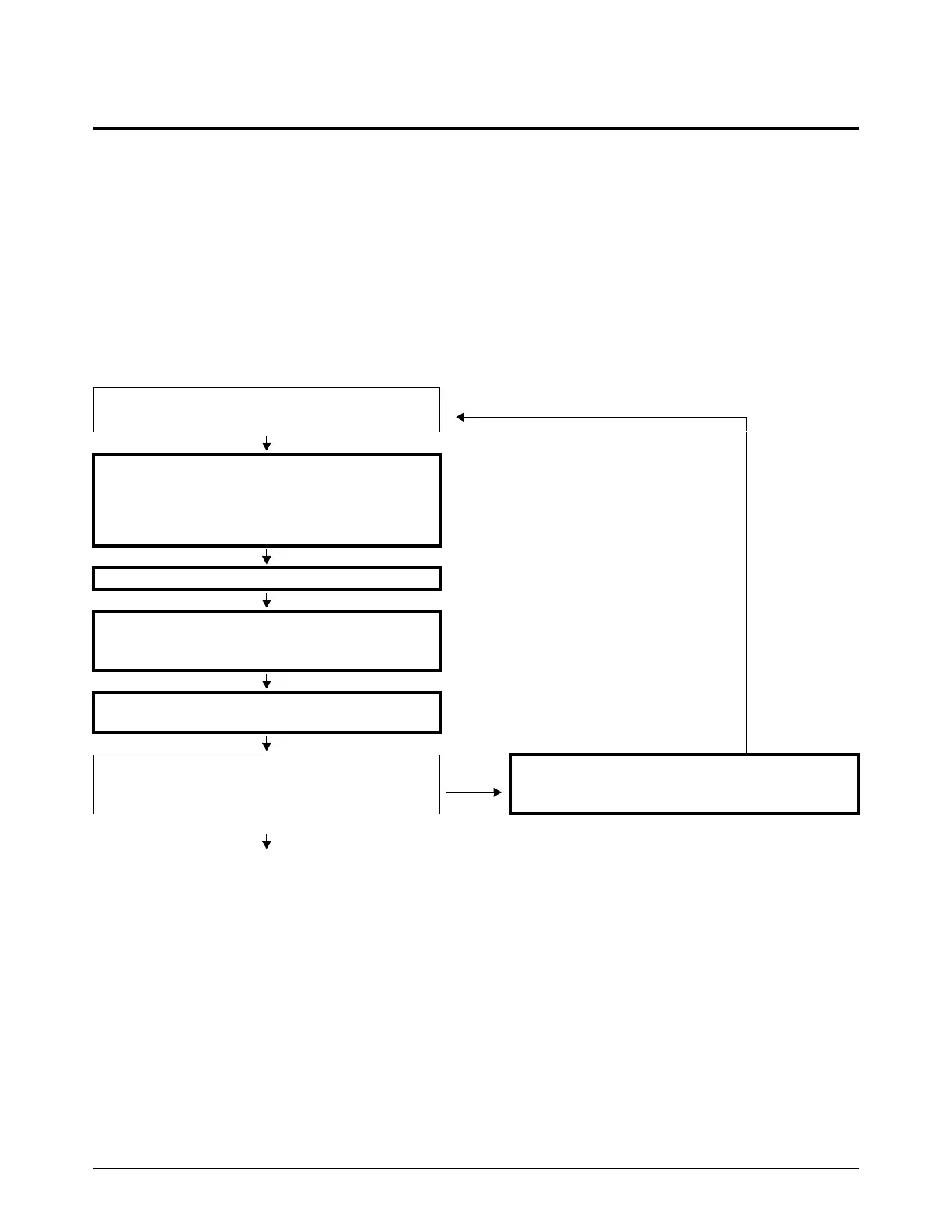
Powerup State (1)
The operator supplies power to the cutting system to start the Powerup State (1).
Power is supplied to the cutting system.
Cutting system operation STARTS.
Make sure that signals are OFF for the following:
• Main contactor
• Coolant pump
• Cooling fans
Establish CAN communication.
Wait for RS-422 serial, EtherCAT, or wireless
communication between the plasma power supply
and CNC or wireless device.
Determine system configuration (number of
choppers and number and type of consoles).
Is Powerup State (1) complete and successful?
No
Diagnose and troubleshoot the problem. Refer to
Diagnostics and Troubleshooting on page 259.
Then, start the Powerup State (1) again.
Yes
Continue to Initial checks State (2) on page 208

 Loading...


