EasyManuals Logo
Home>Hypertherm>Welding System>XPR300

Hypertherm XPR300 User Manual

Hypertherm XPR300
438 pages
To Next Page IconTo Next Page
To Previous Page IconTo Previous Page
Page #59 background imageLoading...
Page #59 background image
Qualifications and Requirements
2
XPR300 Instruction Manual 809480 59
Recommended configuration with the VWI or OptiMix gas connect console
1
2
3
5
6
7
8
a
4
d
e
f
b
A
B
C
D
E
F
≤ 4.5 m (14.8 ft)
≤ 75 m (246.1 ft)
≤ 75 m (246.1 ft)
15m (49.2ft)
c
9
10
11
12
13
A Plasma power supply
B Gas connect console (VWI or OptiMix)
C Torch connect console
D Torch
E Cutting table
F Computerized numeric control (CNC) lead
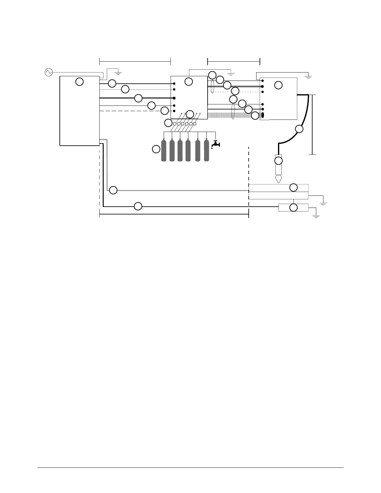
1 Computerized numeric control (CNC) lead
2 Work lead
3 Controller area network (CAN) cable
4 Power cable (120 VAC)
5 Coolant hoses (1 supply, 1 return)
6 Pilot arc lead
7 Negative lead
8 Pilot arc, coolant hose set, shield water assembly
a Pilot arc lead
b Coolant hose set (1 supply, 1 return)
c Shield water hose (VWI or OptiMix)
9 Power, CAN, 5-gas assembly
d Power cable (120 VAC)
e CAN cable
f 5 gas hoses (VWI or OptiMix)
10 Torch lead
11 Regulators
Position a gas regulator within 3 meters (10 feet)
of the gas connect console or take actions to
adjust inlet gas pressures to tolerances specified
in the process gas requirements.
12 Hoses for supply gases
13 Gases and water
VWI: O
2
, air, N
2
, Ar, F5, and water
OptiMix: O
2
, air, N
2
, Ar, F5, water, H
2

Table of Contents

Other manuals for Hypertherm XPR300

Questions and Answers:

Question and Answer IconNeed help?

Do you have a question about the Hypertherm XPR300 and is the answer not in the manual?

Hypertherm XPR300 Specifications

General IconGeneral
BrandHypertherm
ModelXPR300
CategoryWelding System
LanguageEnglish

Related product manuals