Wiring Diagrams
408 809480 Instruction Manual XPR300
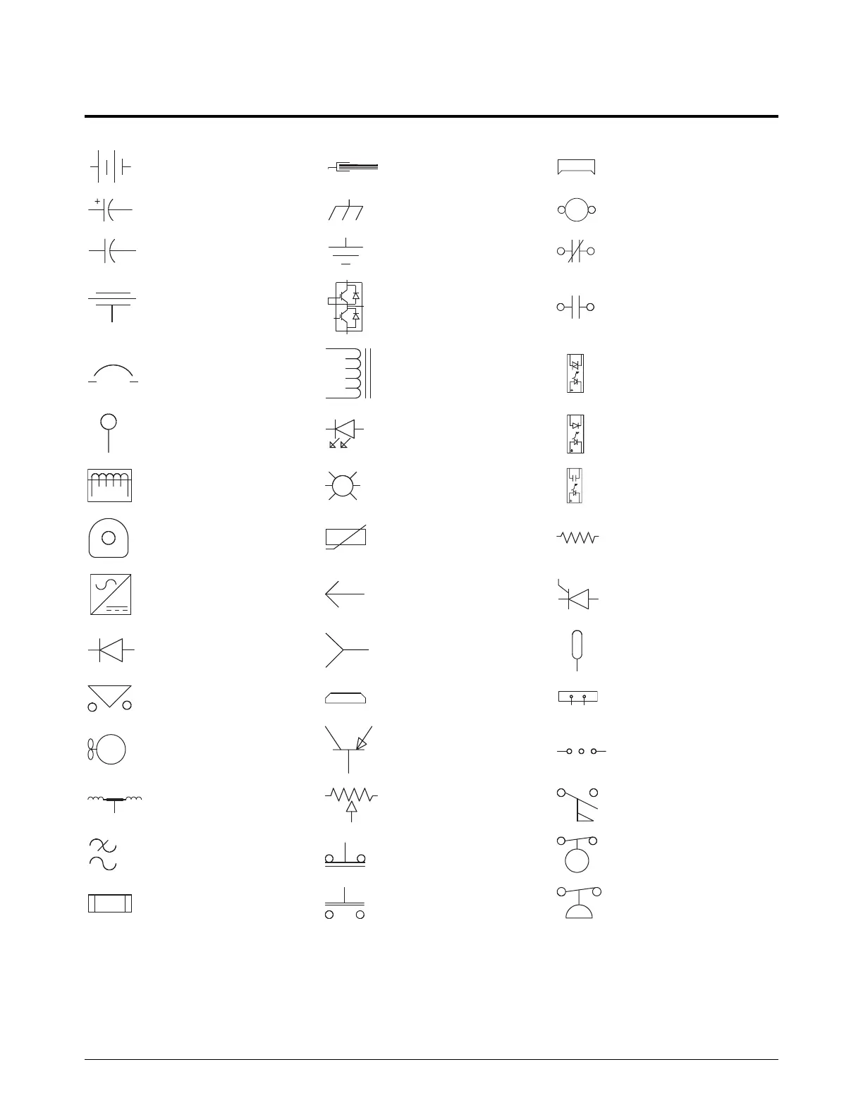
Wiring diagram symbols
Battery Ground clamp Receptacle
Cap, polarized Ground, chassis Relay, coil
Cap, not polarized Ground, earth Relay, normally closed
Cap, feed-through IGBT Relay, normally open
Circuit breaker Inductor Relay, solid state, AC
Coax shield LED Relay, solid state, DC
Current sensor Lamp Relay, solid state
Current sensor MOV Resistor
DC supply Pin SCR
Diode Socket Shield
Door interlock Plug Shunt
Fan PNP transistor Spark gap
Feed-through LC Potentiometer Switch, flow
Filter, AC
Push button,
normally closed
Switch, level,
normally closed
Fuse
Push button,
normally open
Switch, pressure,
normally closed

 Loading...


