Notes:
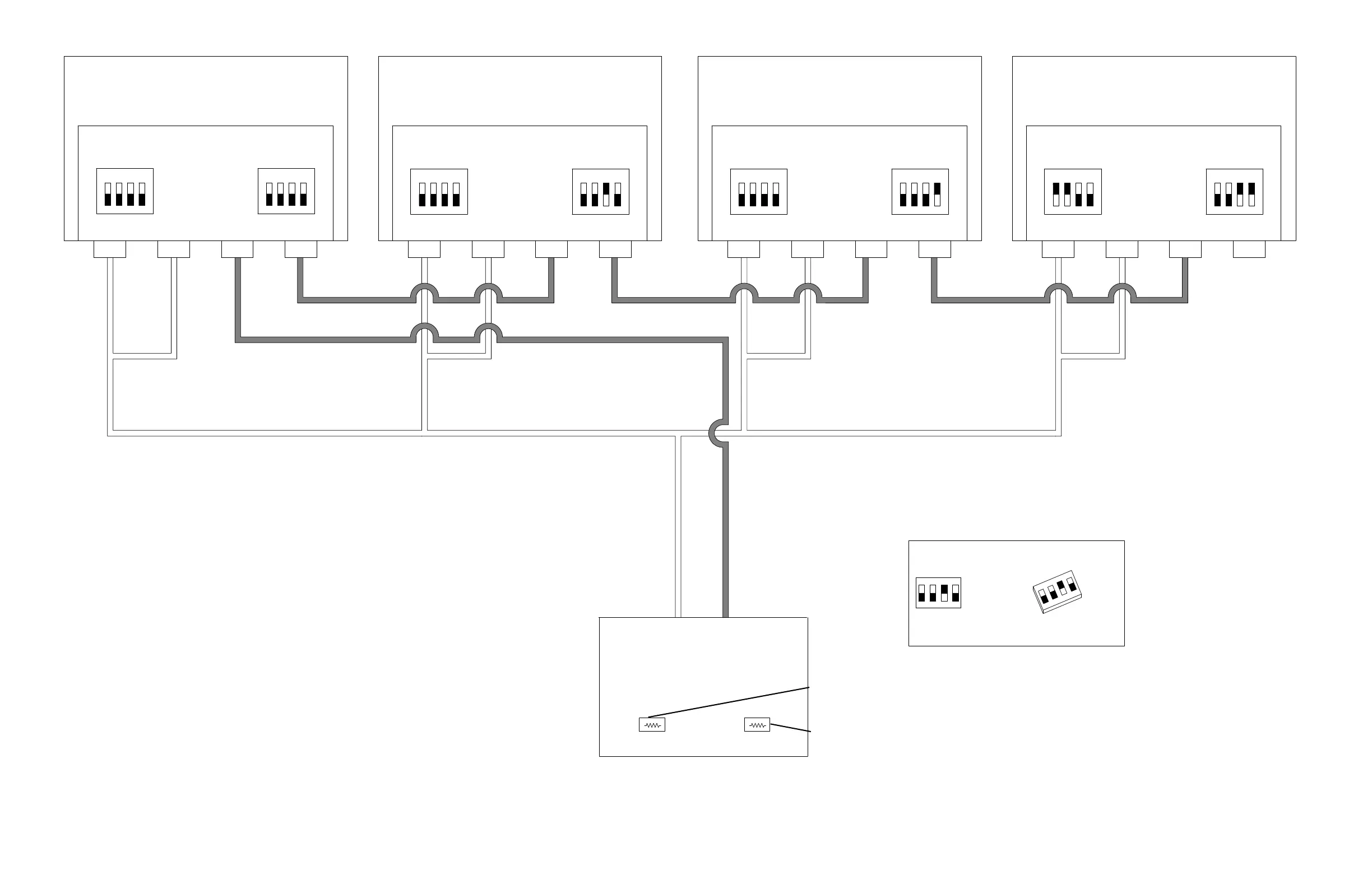
1. For single plasma power supply installations, set Serial terminators (S1) as shown in Unit 4 and
Serial IDs (S2) as shown in Unit 1.
2. On multi-plasma power supply installations see the illustration. Switch S1 position 1 and 2 are
OFF in all plasma power supplies except for the last one where they are set to ON.
Termination resistors (120 ) or termination jumpers must be installed and set at the CNC for
each of the RS-422 RX and TX signal pairs.
3. If a Hypertherm CNC is used and there are intermittent communication failures (PS Link Failure),
try reversing switch S1 position 1 and position 2 on the control board, and the termination jumper
(J6 or J8) on the serial isolation board in the controller. Only remove the termination jumper on the
serial isolation board that is connected to the plasma power supply.
Discrete cable Discrete cable
Serial RS-422 CNC interface
(Customer supplied)
DIP switch setting example
Unit 2
Plasma power supply
Unit 1
Plasma power supply
Unit 3
Plasma power supply
Unit 4
Plasma power supply
Discrete cable
141322
Control board
Serial terminator DIP switch
Serial ID DIP switch
Serial terminator DIP switch
Serial ID DIP switch
Serial terminator DIP switch
Serial ID DIP switch
Serial terminator DIP switch
Serial ID DIP switch
141322
Control board
141322
Control board
141322
Control board
Discrete cable Discrete cable Discrete cable Discrete cable
Serial RS-422 cable
Serial RS-422 cable
Serial RS-422 cable
Serial RS-422 cableSerial RS-422 cable
Switch 3 is in the ON position.
Switches 1, 2, and 4 are in the OFF
position.
TX termination
RX termination
013403

 Loading...


