6
915
KEB COMBIVERT F5
Name: Basis
04.05.04
6
Section PageDate
© KEB Antriebstechnik, 2002
All rights reserved
Chapter
Functional DescriptionSpecial Functions
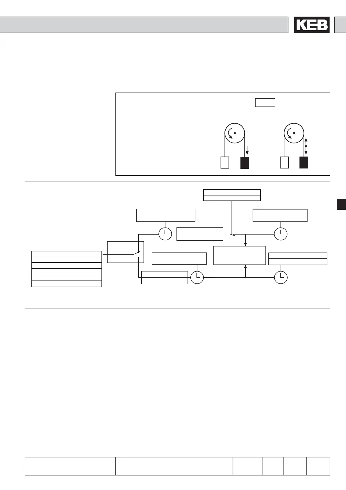
F1>F2
M
H
= F1-F2
F1
F2
M
H
= 0
F1
F2
M
H
M
H
F=F1-F2 F=0
6.9.5 Brake Control
For applications in the field of lifting and lowering the control of the holding brake can
be taken over by this function. A digital output can be programmed as control signal.
The function is set-programmable.
As shown in the opposite graphic a
torque in the amount of the power
difference F1-F2 must be built up, so
that F1 does not slump after releasing
the brake. We call that holding torque.
In the case of the slip-affected three-
phase asynchronous machine a
frequency in the direction of the
holding torque must be preset.
Mode of functioning
Fig. 6.9.5.b Principle of brake control
During the start, triggered by switching on the direction of rotation, a holding torque is
built up first. For it a premagnetizing time (Pn.35) and a starting value (Pn.37) are
preset. As a safety function the monitoring of the acceptance of the inverter can now
be adjusted. Before releasing the brake the utilization is compared with the mimimum
utilization level (Pn.43). If the utilization is less than this level or the hardware current
limit is reached, the error E. br is triggered and the brake remains engaged. If the
utilization acceptance is ensured, the signal for releasing the brake is given after the
time has elapsed. For an additional time (Pn.36: brake release time), in which the
brake is mechanically released, the holding frequency is maintained. It then accelerates
to the adjusted setpoint.
During stopping, triggered by taking away the direction of rotation, the inverter runs
first to the holding frequency (Pn.41). After the brake delay time (Pn.39) the signal for
engaging the brake is given. After expiration of the brake closing time (Pn.40), in
which the brake takes over the utilization, it is decelerated until standstill and the
inverter changes into status LS.
Brake control
Brake release
Pn.34 Brake Control
Off
On; Display boff/bon
On; Display acc, dec, con
On; Display boff/bon; phase check
On; Display acc, dec, con;phase check
Rotation
enabled
disabled
Pn.37 Starting value
Hz or rpm
Pn.39 Brake delay time
0...100s (default 0,25s)
Pn.41 Stop value
Hz or rpm
Pn.35 Premagnetizing time
0...100s (default 1s)
Switching condition 18
„brake opened“
see „digital outputs“
Pn.43 minimum utilization level
0...100 % (default 0 %)
Pn.36 Brake release time
0...100s (default 1s)
Pn.40 Brake closing time
0...100s (default 0,25s)
 Loading...


