6 9
KEB COMBIVERT F5
16
Name: Basis
04.05.04
Chapter Section Page Date
© KEB Antriebstechnik, 2002
All rights reserved
Functional Description Special Functions
LS
facc fcon fcon
boff boff boff
facc fcon rdec
fcon fcon fdec
LS
bon bon bon
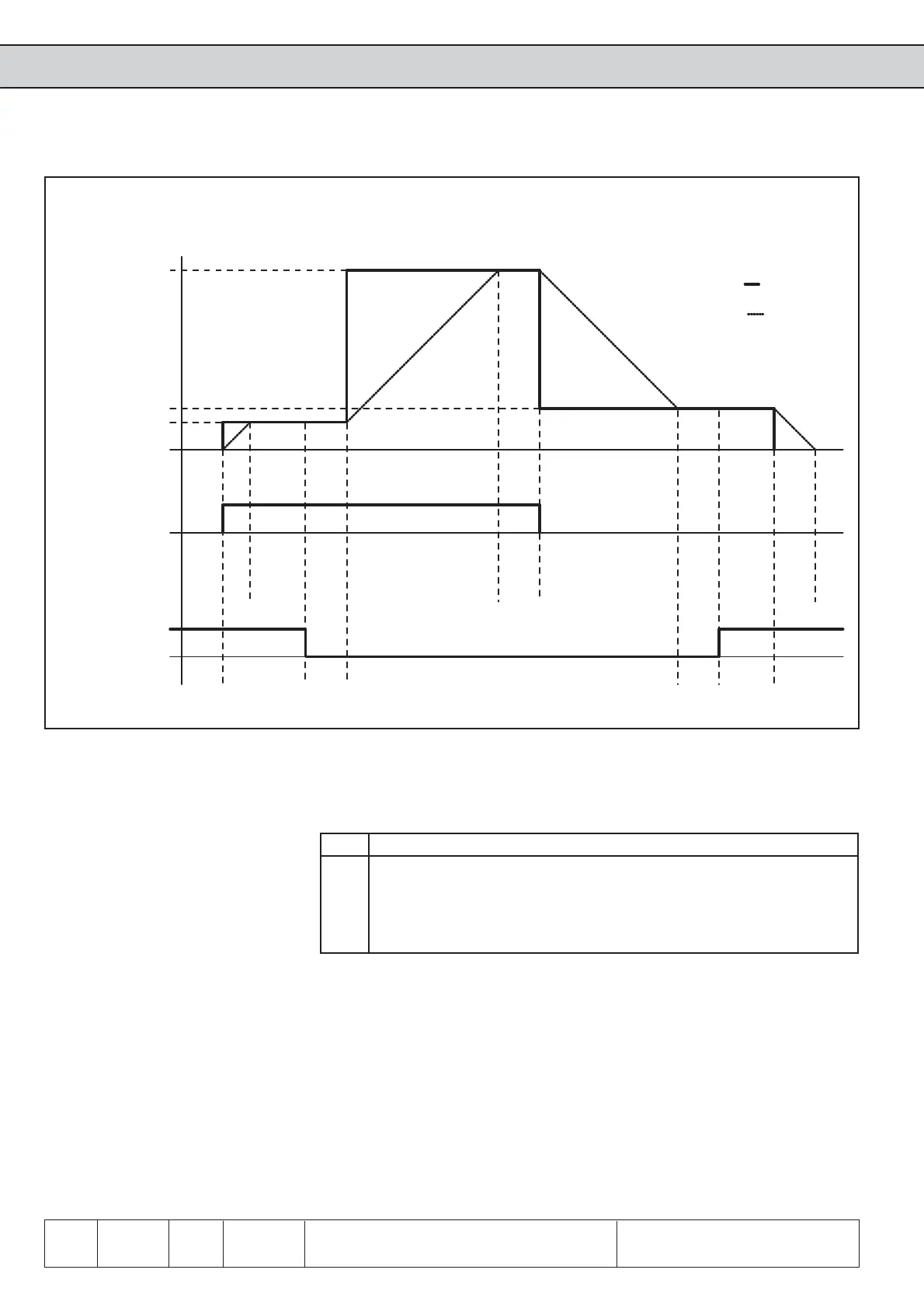
6.9.5.c Example: Setpoint direction forward; positive holding frequency
The function is activated or deactivated with this parameter. In addition the status
display can be changed over. If the output phase monitoring is activated, each output
phase is checked before acceleration to the starting value. If one phase is missing or
in case of wrong wiring in the inverter E.br is triggered. Pn.34 is set-programmable.
Value Function
0 Function deactivated (default)
1 Brake control active, display boff/bon
2 Brake control active, display acc/dec/con
1 Brake control active, display boff/bon, with phase monitoring
2 Brake control active, display acc/dec/con, with phase monitoring
The status display during the holding phases depends on the setting of the mode for
the brake control (see Fig. 6.9.5.c).
At - Pn.34 =1/3 the status boff (release brake) or bon (engage brake) is displayed.
- Pn.34 = 2/4 the normal ramp status is displayed.
In addition to it a digital output (switching condition 18) is to be programmed for the
control (see Chapter 6.3).
For the monitoring of the utilization acceptance through the inverter a minimal utilization
level can be adjusted in this parameter. When the brake shall be released during the
start, the utilization may not be less than the adjusted level. Otherwise the error E.br
is triggered. Reaching the hardware current limit the error E.br is triggered too. The
monitoring is deactivated when Pn.43 is set to 0.
Mode brake control
(Pn.34)
Minimal utilization level
Error message E.br
(Pn.43)
Set frequency
Stop value
Pn.41
Starting value
Pn.37
Rotation setting
FOR
Inverter state
closed
Brake
opened
set frequency
brake control
real frequency
Premagne-
tizing time
Pn.35
Brake
release
time
Pn.36
Brake
delay
time
Pn.39
Brake
release
time
Pn.40
 Loading...


