27
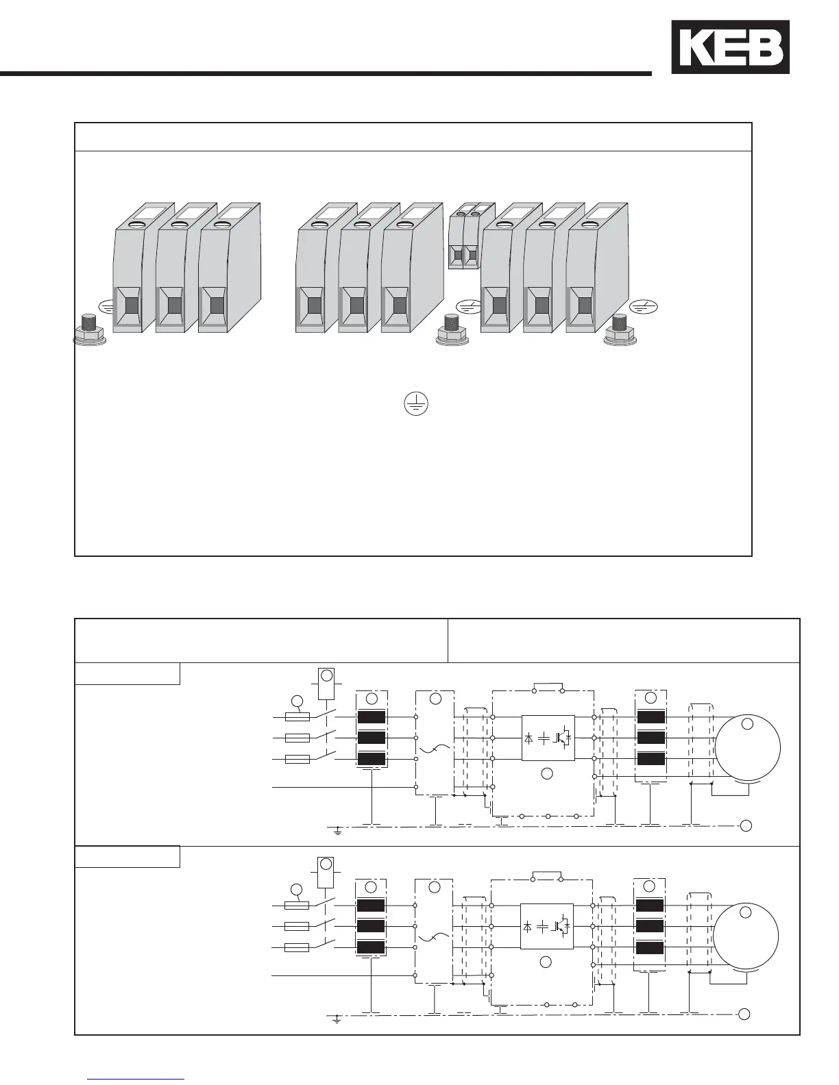
Power Circuit Terminals
Housing size R and U
T1, T2 Connection for temperature sensor
U, V, W Motor connection
Connection for earth ground M8 stud.
Note: Ground Stud and Nut shall be connected with UL
Listed Ring Connectors (ZMVV), rated suitable.
Note always verify input voltage with name plate for proper connection
L1, L2, L3 3 phase supply voltage
+ +, - - DC supply connection
+ +, PB Connection for braking resistor
Terminal Tightening Torque: R housings size <= 22: 53 inlb (6Nm)
R & U housings size 23/24: 133inlbs (15Nm)
U housings sizes > 24: 221inlbs (25Nm)
Ground nut on R & U housings: 89inlbs (10Nm)
2.5 Connection of the power circuit
If the supply voltage is connected to the motor
terminals, the unit will be destroyed!
Pay attention to the supply voltage 230/480V
and the correct polarity of the motor!
See technical data in Section 2.1-2.2 to match the wiring diagram to inverter size and housing type.
Wiring diagram 1
Wiring diagram 2
L1
L2
L3
L1
L2
U
V
W
M
3
~
T1
T2
U
V
W
U1
V1
W1
L1
L2
L3
PA
PB
+
3
2
4
1
5
7
8
6
L3
GND
GND
GND
GND
GND
L1
L2
L3
L1
L2
U
V
W
M
3
~
T1
T2
U
V
W
U1
V1
W1
L1
L2
L3
+
PB
+
3
2
4
1
5
7
8
6
-
-
+
L3
GND
GND
GND
GND
GND
Verify input voltage with name plate for proper connection 230V or 480V
 Loading...


