30
0
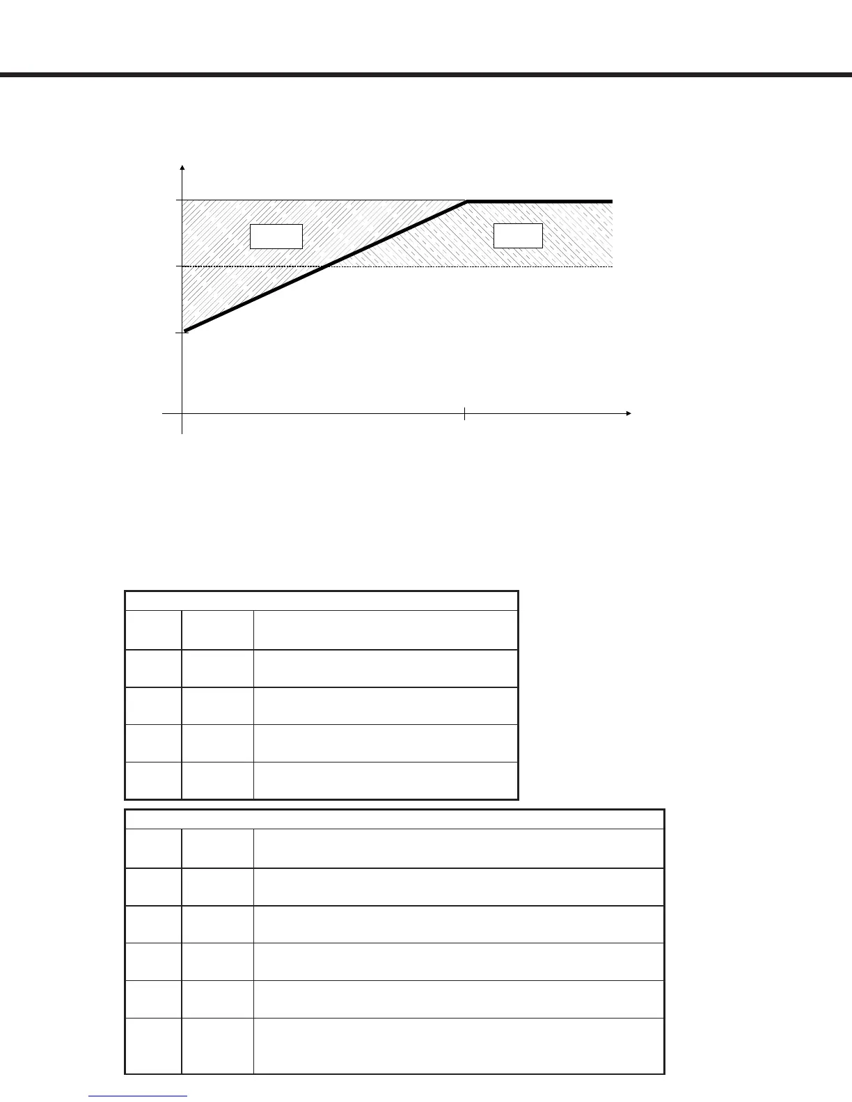
3 Hz
150%
105%
E. OL
E. OL2
f [Hz
Load [%]
2.7 Low Speed Overload
Permanent
current
(0 Hz)
(E.OL2)
230V Maximum stall current (amps at 0Hz)
Inverter Carrier Inverter Size
Housing Frequency 13 14 15 16 17 18 19 20 21
E 8 kHz 24 24
16 kHz 16.8 16.8
G 8 kHz 33 31
16 kHz 33 26
H 8 kHz 53 72.5 109
16 kHz 53 73 92
R 8 kHz 84 100 115 145 180
16 kHz 50 70 70 102 102
460V Maximum stall current (amps at 0Hz)
Inverter Carrier Inverter Size
Housing Frequency 13 14 15 16 17 18 19 20 21 22 23 24 26 26
E 8 kHz 12 17 17
16 kHz 12 10 10
G 8 kHz 12 17 19 22.0
16 kHz 12 12 8.4 9.5
H 8 kHz 24 33 42 50 54 83
16 kHz 15 20 25 30 36 45
R 8 kHz 50 60 75 81 115 165
16 kHz 40 27 34 45 63 150
4 kHz 165 198 330 330
U 8 kHz 150 180 180 225
16 kHz - - -
Overload Characteristic
At low speeds (below 3 Hz) the rms current owing through the power transistors is higher,
reaching 1.4 times the rated 60Hz rms value. This is caused by the low frequency sine wave
created by the PWM. As a result, the continuous output current must be limited at low speeds
to prevent the power transistors from overheating. The COMBIVERT F5 will drop the carrier
frequency to 4kHz if necessary to be able to continue to provide current to the motor. Once the
output frequency rises above 3Hz or the current drops below the levels listed below, the carrier
frequency will be returned to the higher value.
 Loading...


