32
Installation and Connection
In order to prevent a malfunction caused by interference voltages on the
control inputs, the following steps should be observed:
• Establish a true earth ground for all ground connections!
• Do not connect drive signal commons to earth ground!
• Use shielded cable with twisted pair wires!
• Terminate shield wires to earth ground, only at inverter!
• Separate control and power wires by 8" or more!
• Control and power wires should cross at a right angle!
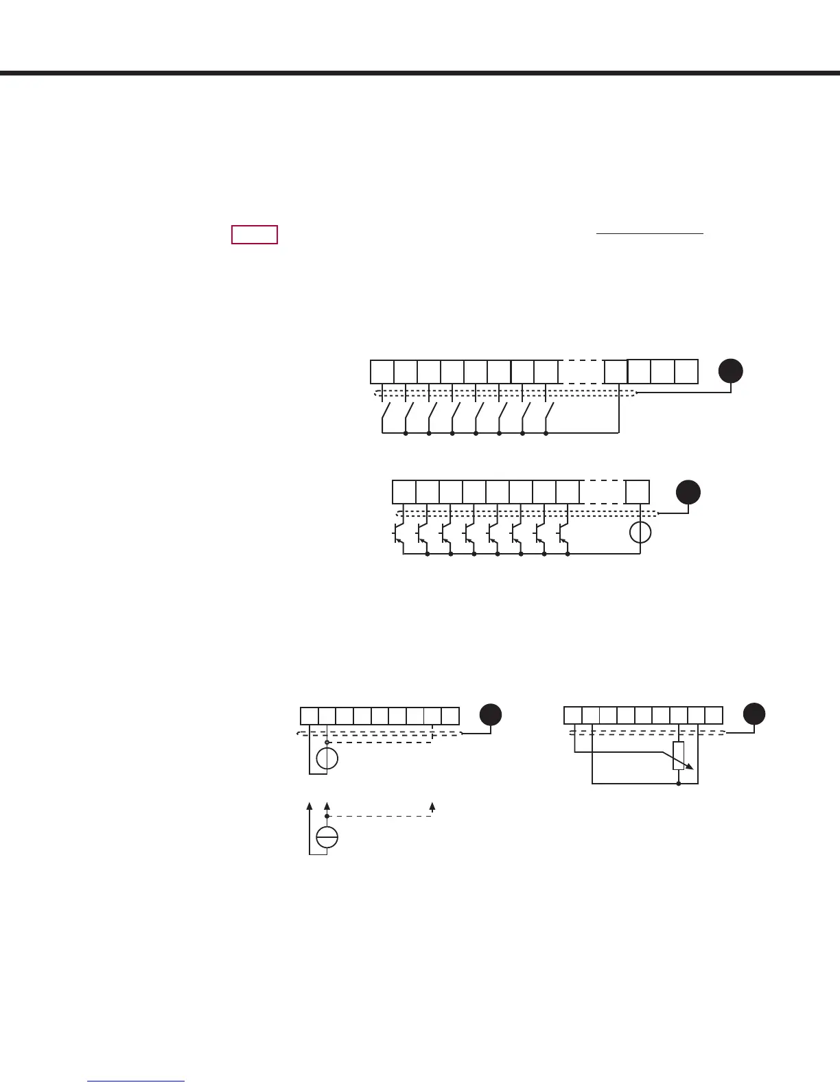
3.1.4 Analog Inputs
3.1.3 Digital Inputs
EMC
Use of external voltage supply
Use of internal voltage supply
Connect unused analog inputs to common to eliminate noise signals!
X2A
123456789
R = 3...10 kW
GND
X2A
123456789
GND
0...±10 VDC
Ri = 55 kW
+
+
0(4)...20 mADC
Ri = 250 W
Ri = 2.1 k
*
*
20...30 VDC
Regulated
10 11 12 13 14 15
GND
X2A
16 17 23
+
10 11 12 13 14 15
GND
X2A
16 17 20
21 22 23
Speed Pattern, Torque
Command
3.1.2 Connection of the
control signals
 Loading...


