31
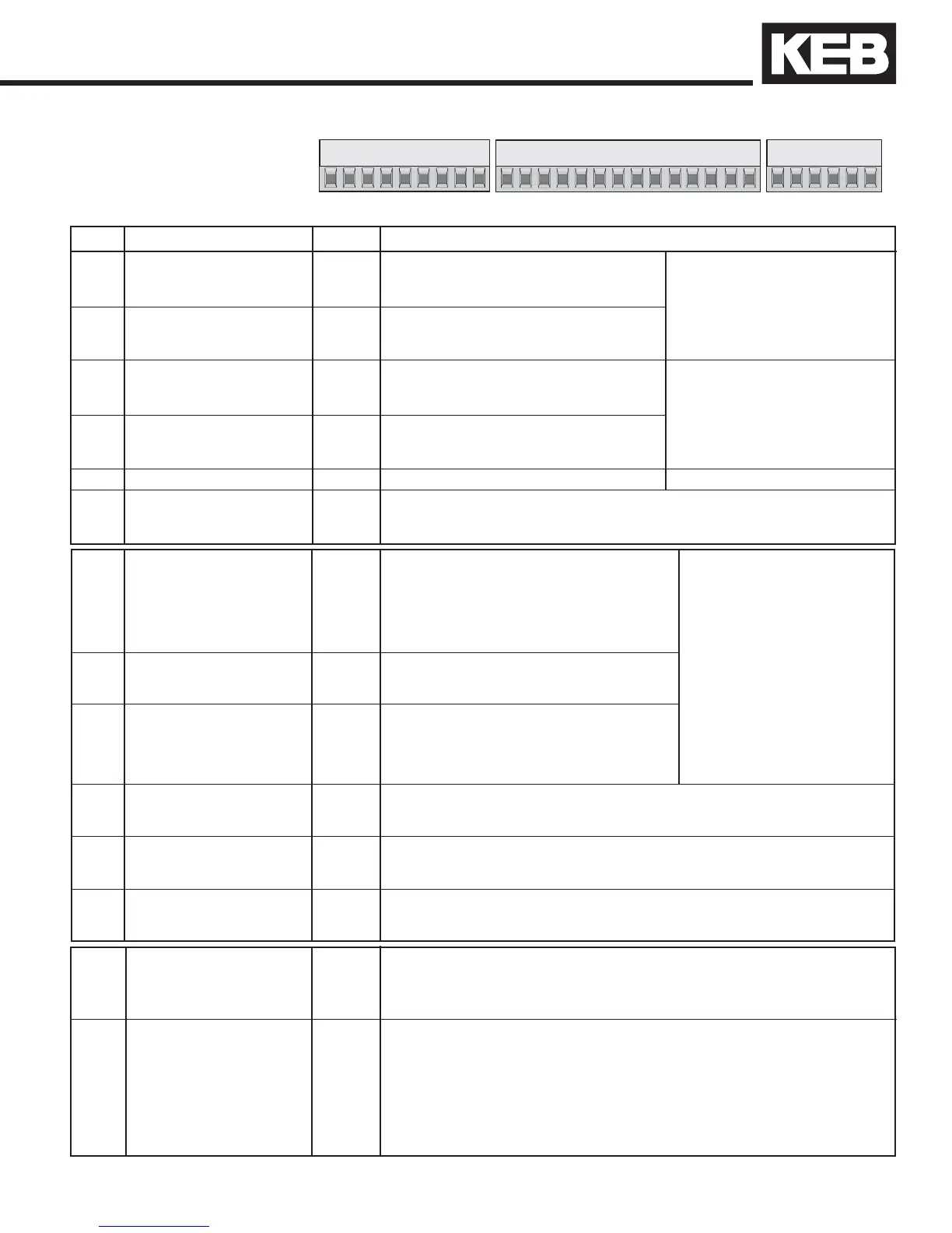
3.1.1 Terminal Strip
Connections
3.1 Control Circuit
123456789
10 11 12 13 14 15 16 17 18 19 20 21
22 23 24 25 26 27 28 29
X2A
PIN Function Name Description
1 Analog input 1 + AN1+ Pattern speed input or resolution: 12 Bit
2 Analog input 1 - AN1- torque command input
3 Analog input 2 + AN2+ Pre-torque input scan time: 1 ms
4 Analog input 2 - AN2-
5 Analog output 1 ANOUT1 Analog output of the real speed Voltage range: 0...±10V
0...±10 VDC ( 0...± 100 % ) Ri=100 kOhmresolution: 12Bit
6 Analog output 2 ANOUT2 Analog output of the motor torque
0 ... 10 VDC ( 0 ... 2 x T
Rated (motor)
)
7 +10V Output CRF Analog supply voltage for speed ref. +10 VDC +5%, max. 4 mA
8 Analog Common COM Common for analog in- and outputs
9 Analog Common COM Common for analog in- and outputs
10 Optional Function
OPT Inputs 11,12,13 provide binary coded speed
11 Leveling Speed S
L
selection of up to 7 speeds. See parameter
12 High Leveling Speed S
HL
LF.2. With analog control (LF.2=A SPd or AbSPd)
13 High Speed S
H
these inputs are not used! Ri = 2.1 kOhm
14 Up U Preset rotation; scan time: 1 msec
15 Down D "Up" has priority digital lter reduces false
16 Drive Enable ST Enable/Disable; response time < 1msec; trigger due to relay chatter.
enable instantly turns off motor current lter time: 20msec (adjustable)
17 Reset RST Clears a drive error ( E.XXX)
18 Digital Out 1 O1 At speed signal (turns off if the actual speed deviates from the set speed)
19 Digital Out 2 O2 Fault signal (activates when there is a drive fault)
20 24V-Output V
out
Approx. 24V output (max.100 mA load)
21 20...30V-Input V
in
Voltage input when an external 24VDC supply is used
22 Digital Common 0V Common for digital in-/outputs
23 Digital Common 0V Common for digital in-/outputs
24 RDY Relay NO Ready; relay drops when a drive fault occurs (E.XX).
25 NC Picks after fault is cleared with RST input or power cycle
26 max. 30 V DC, 1 A COM See Parameter do.82
27 DRO Relay NO Drive On; relay picks after all of the follow conditions are met:
28 NC enable picked, direction picked, motor phase current check passes.
29 max. 30 V DC, 1 A COM Relay drops when one of the following occurs: enable dropped, direction
dropped and actual speed is zero, drive fault (E.XX).)
See Parameter do.83
3.0 Installation and Connection
 Loading...


