Model 6220/6221 Reference Manual Status Structure 11-7
Return to Section 11 topics
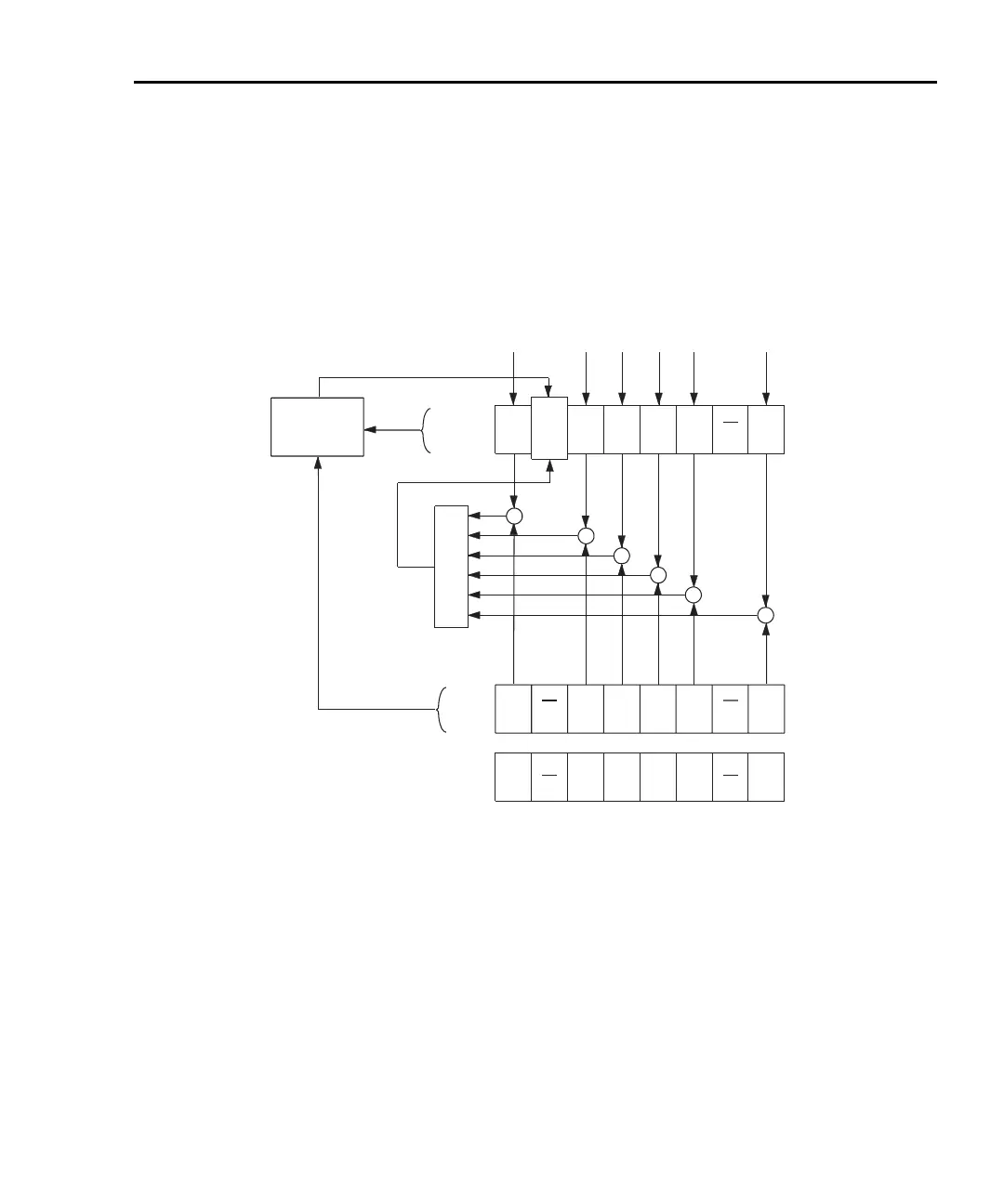
Status byte and service request (SRQ)
Service request is controlled by two 8-bit registers: the status byte register and the
service request enable register. Figure 11-3 shows the structure of these regis-
ters.
Figure 11-3
Status byte and service request
Status byte register
The summary messages from the status registers and queues are used to set or
clear the appropriate bits (B0, B2, B3, B4, B5, and B7) of the status byte register.
These summary bits do not latch and their states (0 or 1) are solely dependent on
the summary messages (0 or 1). For example, if the standard event register is
Status Summary Messages (6)
OSB
(B7)
RQS
(B6)
MSS
ESB
MAV
(B4)
QSB
(B3)
EAV
(B2)
(B1)
(B0
OR
* SRE
* SRE?
Status Byte
Register
Service Request
Enable Register
OSB = Operation Summary Bit
MSS = Master Summary Status
RQS = Request for Service
ESB = Event Summary Bit
MAV = Message Available
QSB = Questionable Summary Bit
EAV = Error Available
MSB = Measurement Summary Bit
& = Logical AND
OR = Logical OR
OSB
(B7) (B6)
ESB
(B5)
MAV
(B4)
QSB
(B3)
EAV
(B2)
(B1)
(B0)
&
&
&
&
&
MS
MSB
&
128
(2
7
)
32
(2
5
)
16
(2
4
)
8
(2
3
)
4
(2
2
)
1
(2
0
)
Decimal
Weights
* STB?
Serial Poll
Service
Request
Generation
Test Equipment Depot - 800.517.8431 - 99 Washington Street Melrose, MA 02176 - TestEquipmentDepot.com

 Loading...