Theory of Operation
6-11
6.4.7 External control signals
For the following discussion, refer to BNC board sche-
matic 7001-166 and micro-DIN board schematic 7001-
186.
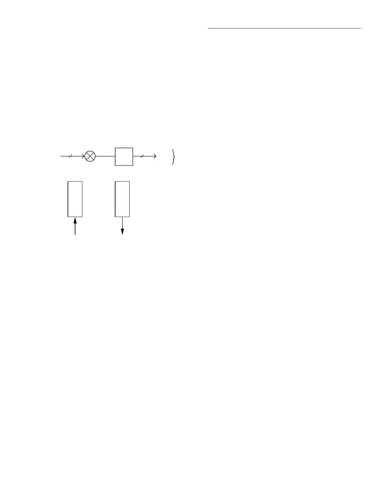
External signals are CHANNEL READY and EXTER-
NAL TRIGGER, as shown in Figure 6-9, and DIGITAL
I/O, as shown in Figure 6-10.
CHANNEL READY and EXTERNAL TRIGGER are
TTL-compatible, and support communication with ex-
isting instrument products or other user-supplied
equipment through BNC connectors.
TRIGGER LINK consists of six TTL-compatible signals
that can be bused between instruments via a pair of 8-
pin TRIGGER LINK IN and TRIGGER LINK OUT mi-
cro-DIN connectors located on the Model 7001 rear
panel. The TRIGGER LINK can be programmed in
asynchronous mode to operate as an additional
CHANNEL READY or EXTERNAL TRIGGER signal,
or in semi-synchronous mode.
DIGITAL I/O has four programmable outputs, one
TTL output, and an additional line that provides exter-
nal pull-up voltage for the outputs. DIGITAL I/O is
provided through a third 8-pin micro-DIN connector
located on the Model 7001 rear panel.
All external control signals can be controlled through
the front panel or programmed via the IEEE-488 bus.
6.4.8 IEEE-488 interface
The IEEE-488 interface is composed of three ICs. A
9914 General-Purpose Interface Adapter (GPIA) auto-
matically performs many bus control, data I/O, and
handshaking functions, thus minimizing overhead to
the system microprocessors. Bus drive capabilities are
provided by a 75161 and 75160 (U100 and U101). The
75161 supports bus management and handshake lines,
while the 75160 drives the data lines.
6.4.9 Power supplies
The major component of the power supply is a univer-
sal AC-input switching power supply. This supply con-
tains an internal line fuse and an autoranging input
which automatically adjusts to the voltage of the input
mains. The power switch is located on the BNC board,
and actuated from the front panel through a mechani-
cal extension of the ON/OFF button. The AC input re-
ceptacle is also wired to the BNC board; from here it is
passed directly to the power supply board.
The switching supply provides regulated +6VDC and
+14.6VDC for the relay power supply circuitry. These
voltages are routed to the switch card via the digital
board and backplane. On the digital board, the +6V is
regulated to +5V using two LM2940 regulators. One
LM2940 supplies +5V to the digital display, backplane,
switch cards, and micro-DIN boards, while the other
LM2940 provides +5V to U117, the VFD supply mod-
ule. The VFD supply module generates +60VDC and
5VAC for the display board.
AC
Mains
2
Power Switch
EMI
Filter
2
AC
Mains
To
Power
Supply
CH RDY EX TRIG
BNC
From µDIN Board To µDIN Board
BNC
Figure 6-9
BNC board block diagram
Artisan Scientific - Quality Instrumentation ... Guaranteed | (888) 88-SOURCE | www.artisan-scientific.com
 Loading...

