Front Panel Operation
4-46
4.9.2 Digital input channel
The Model 7001 has one digital input channel that is
used to read a TTL input level. A TTL high on the input
will be read as “ON”.
The front panel MENU feature reads the level of the
digital input channel.
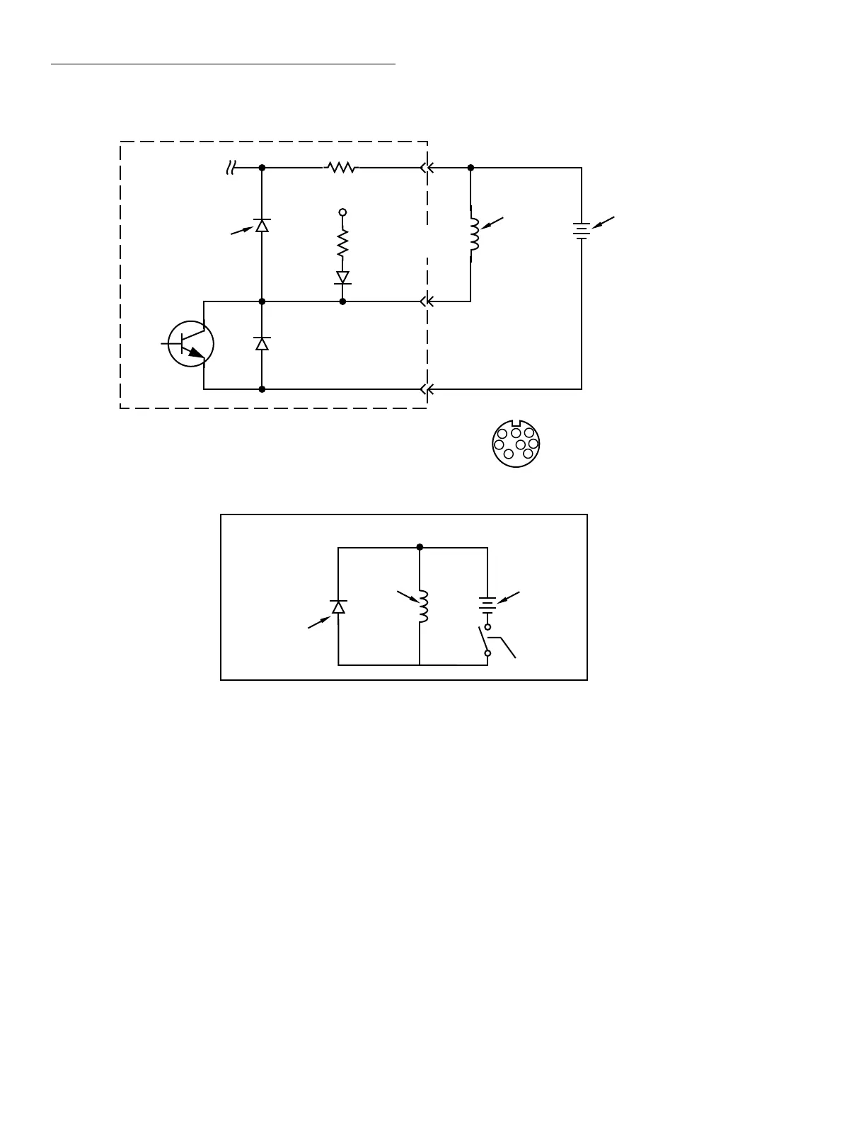
Figure 4-10
Sample externally powered relay
To other three
digital outputs
+5V
10Ω
Digital Output #1
Flyback Diodes
Pin 3 - External Voltage Flyback
connection (+5 to +30V)
Pin 4 - Digital Output #1
Pin 8 - Digital Ground
Relay Coil
(+)
(-)
External Power
(+5V to +30V)
10kΩ
Pull Up Resistor
Relay Coil
(+)
(-)
External Power
(+5V to +30V)
Flyback Diodes
Equivalent Circuit
Model 7001
Transistor Switch
DIGITAL
OUT
5
1
6
(Connector J1007)
2
3
4
7
8
4.9.3 I/O port connections
The DIGITAL I/O port is located on the rear panel as
shown in Figure 4-11. This drawing also provides the
pin identification for the 8-pin micro DIN female recep-
tacle. Since the DIGITAL I/O receptacle is the same as
the TRIGGER LINK receptacle, you can use a trigger
link cable (Keithley Model 8501) to make connections.
By cutting a trigger link cable in two, it is possible to
hard-wire the unterminated end directly to an external
digital circuit.
Artisan Scientific - Quality Instrumentation ... Guaranteed | (888) 88-SOURCE | www.artisan-scientific.com
 Loading...

