Front Panel Operation
4-43
RESTRICTED-CHANNELS Used to designate
channels that cannot be closed from either the front or
over the bus. This is primarily used as a safety feature
to prevent the inadvertent closing of a channel(s) that
could cause damage to instrumentation or DUT (i.e.
shorting a power supply in a matrix test system).
If you specify a channel to be restricted and it is already
included in the Scan List and/or a Channel Pattern, a
saved state error (+510) occurs and the entire Scan List
and/or Channel pattern is cleared (lost)/ See para-
graphs 4.5.2 and 4.5.5 for more information.
Perform the following steps to define the restricted
channels:
1. With the CHANNEL RESTRICTIONS menu dis-
played, place the cursor on RESTRICTED-CHAN-
NELS and press ENTER. The following message
will be displayed:
RESTRICTED CHANNELS
SELECT CHANNELS
2. Use the keypad to enter the channel list and press
EXIT.
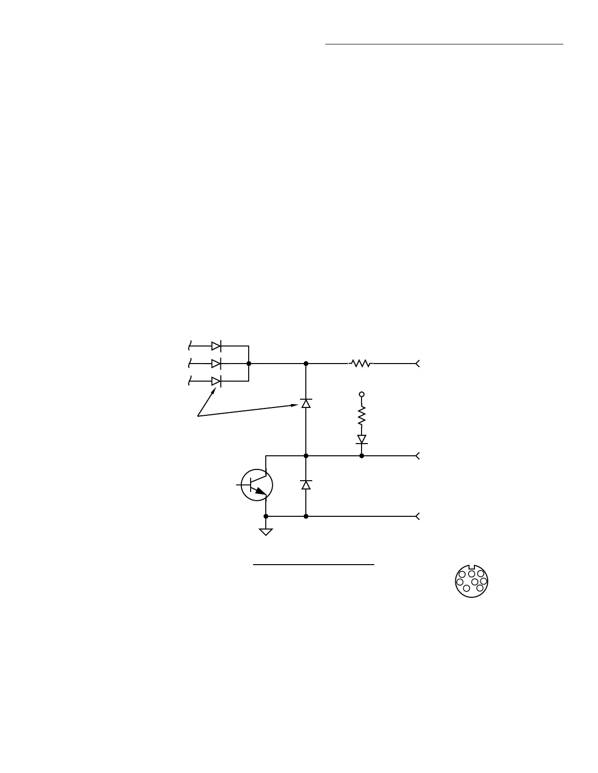
4.9 Digital I/O port
The Model 7001’s Digital I/O port is an 8-pin micro-
DIN socket (J1007) located on the rear panel. Figure
4-9 shows a simplified schematic containing pin des-
ignations.
Figure 4-9
Digital I/O port simplified schematic
Pin 5 - Digital Output #2
+5V
10Ω
Digital Output
Flyback Diodes
10kΩ
Pin 6 - Digital Output #3
Pin 7 - Digital Output #4
DIGITAL
OUT
5
1
6
(Connector J1007)
Pin 3 - External Voltage Flyback
connection (+5V to +30V)
Pin 4 - Digital Output #1
Pin 5 - Digital Output #2
Pin 6 - Digital Output #3
Pin 7 - Digital Output #4
Pin 8 - Digital Ground
2
3
4
7
8
1 = Digital In
2 = N/C
3 = V
ext
fly-back connection (+5V to +30V)
4 = Digital Output #1
5 = Digital Output #2
6 = Digital Output #3
7 = Digital Output #4
8 = Digital Ground
Pin Designations
Artisan Scientific - Quality Instrumentation ... Guaranteed | (888) 88-SOURCE | www.artisan-scientific.com
 Loading...

