Front Panel Operation
4-51
4.11 Trigger Link
The Model 7001 has enhanced external triggering capa-
bilities using the Trigger Link. The Trigger Link has six
lines allowing up to six instruments to be controlled
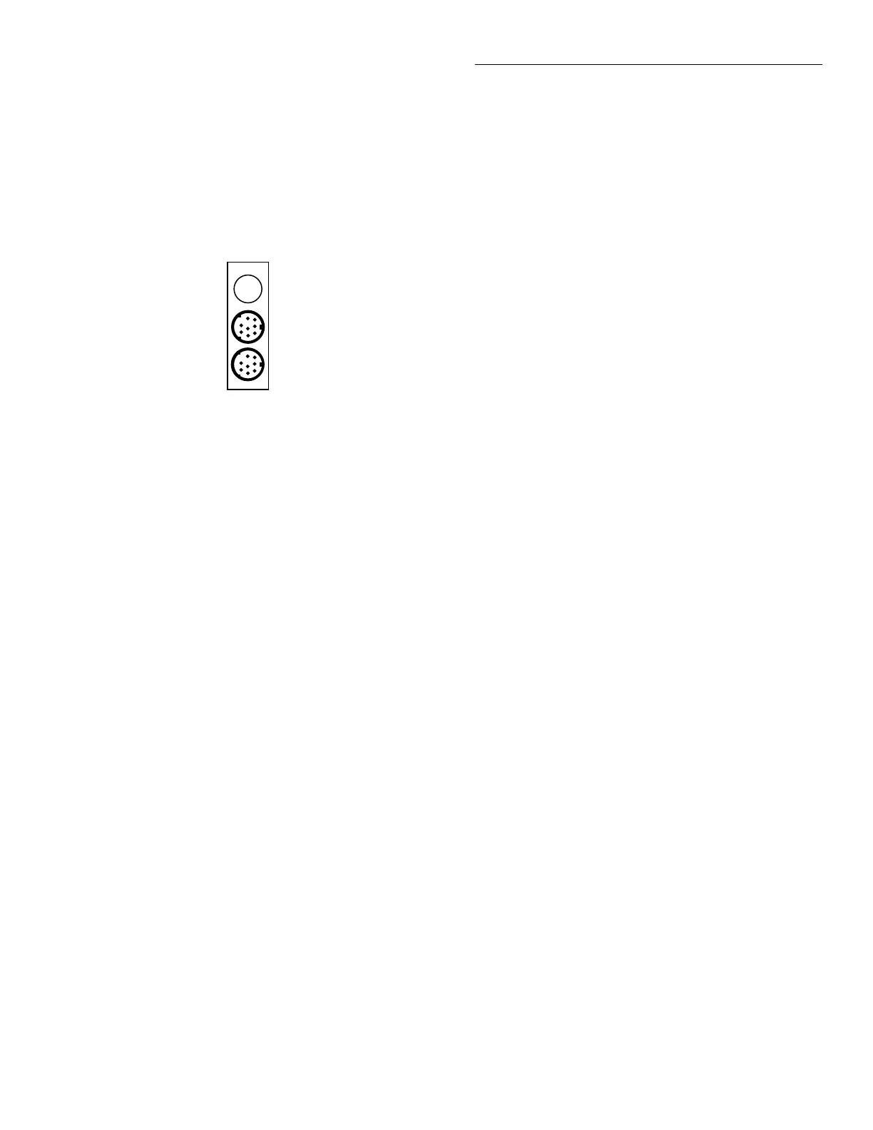
over this trigger bus. The micro 8-pin DIN sockets used
for the Trigger Link are shown in Figure 4-18.
NOTE
The two rear panel Trigger Link con-
nectors are actually connected in par-
allel to each other. Thus, the IN and
OUT labels are a misnomer. It does not
matter which connector you use when
connecting the Trigger Link to another
instrument.
CAUTION
Trigger Link and the Digital I/O port
use the same type of connector. To
prevent possible damage, do not con-
nect the Digital I/O to the Trigger
Link. Also, when connecting an ex-
ternal circuit to the Digital I/O, take
care to not accidentally connect it to
the Trigger Link.
In general, Trigger Link input triggers to the Model
7001 are used to control scan operation. In order for the
Model 7001 to respond to Trigger Link compatible trig-
gers, the appropriate layers of the scan must be pro-
grammed for it. For example, if you want Trigger Link
input triggers to control the channel scan process, you
must program Channel Spacing for TRIGLINK trigger
events. Typically, a Trigger Link output trigger from
the Model 7001 would be used to trigger another in-
strument to measure the currently selected channel.
There are two modes of operation for Trigger Link;
asynchronous and semi-synchronous. In the asynchro-
nous mode, separate lines are used for input and out-
put triggers, and in semi-synchronous mode, the same
line is used for both input and output triggers.
4.11.1 Asynchronous operation
In the asynchronous operating mode, Trigger Link
functions fundamentally in the same manner as Exter-
nal Triggering (see paragraph 4.10). Like External Trig-
gering, the asynchronous mode uses separate lines for
input and output triggers. Also, the asynchronous
mode uses the same TTL-compatible pulses as External
Triggering. The input trigger specifications for asyn-
chronous mode are shown in Figure 4-14 and the out-
put trigger specifications are shown in Figure 4-15.
For typical Asynchronous Trigger Link operation, the
channel layer of the scan is configured with Channel
Spacing set to TRIGLINK and Triggerlink Mode set to
Asynchronous. You must also select input and output
lines for the channel layer. Input and output triggers
can be set to any of the six lines, but they cannot use the
same line. For example, if you select line #1 for input
triggers, then output triggers must use one of the other
five lines (#2 through #6). During operation in the
channel layer, each Trigger Link input trigger will close
a channel in the scan. After the relay settles, and the
user programmed DELAY (see paragraph 4.7) times
out, the Model 7001 will output a Trigger Link trigger
(typically to a DMM to make a measurement). The
channel layer is configured using the CONFIGURE
SCAN menu (see paragraph 4.8.1).
The scan layer and/or arm layer can also be pro-
grammed for TRIGGER LINK; Scan Spacing is set to
TRIGLINK, and ARM SPACING is set to TRIGLINK.
When using Trigger Link in these layers, you must also
select input and output lines as you did in the channel
layer. Keep in mind that you can use the same lines in
the scan and arm layers that you selected in the chan-
nel layer.
Figure 4-18
Trigger link connectors
TRIGGER LINK
I
N
O
U
T
Artisan Scientific - Quality Instrumentation ... Guaranteed | (888) 88-SOURCE | www.artisan-scientific.com
 Loading...

