- 105 -
KD 702_1003_1404 Workshop Manual_cod. ED0053029340_1° ed_
12
223
220
222
221
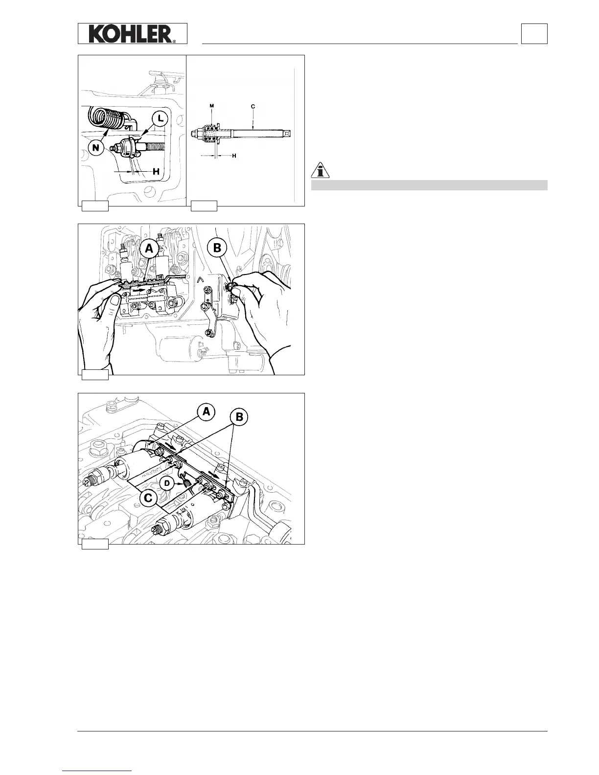
Setting the stop
Remove the rocker arms cover and completely unloosen screw
B.
Push rod A to the right and keep it in this position; see gure.
Tighten screw B until it touches rod A.
Release rod A and tighten again screw B by a 0.5÷1.0 turn.
Tighten the lock nut.
Pump/injector unit timing with speed governor
- Loosen the screws C of each pump/injector unit.
- If it is not connected, connect spring D to rod A (with this
operation the speed governor blocks are closed).
- Move plates B of each pump/injector unit rightwards; see
gure (with this operation the pumps/injector unit are at their
maximum delivery).
- Tighten screws C at 1.1 Nm. Re-balance the deliveries.
Note: Spring D is the start-up fuel supplement spring: with the
engine stopped pull rod A to the right by bringing the
pump/injector unit delivery to the maximum value, until
the speed governor comes into operation with the engine
running
Injection pump ow limiter and engine torque gearing device
Flow limiter C has the function of limiting the injection pump’s
maximum delivery.
The same mechanism acts also as a torque gearing device.
Indeed, under torque, spring N operating lever L overcomes the
resistance of spring M located in the plunger barrel.
The stroke H that the torque gearing device allows to be carried
out by lever L, will increase the injection pump delivery and the
torque will hit its maximum value.
Important
The stroke H varies depending on which engine torque gearing
device is tted on the engine.
Settings
 Loading...