- 40 -
KD 702_1003_1404 Workshop Manual_cod. ED0053029340_1° ed_ rev. 00
8
1
4
2
7
6
5
13
10
3
9
8
11
12
6
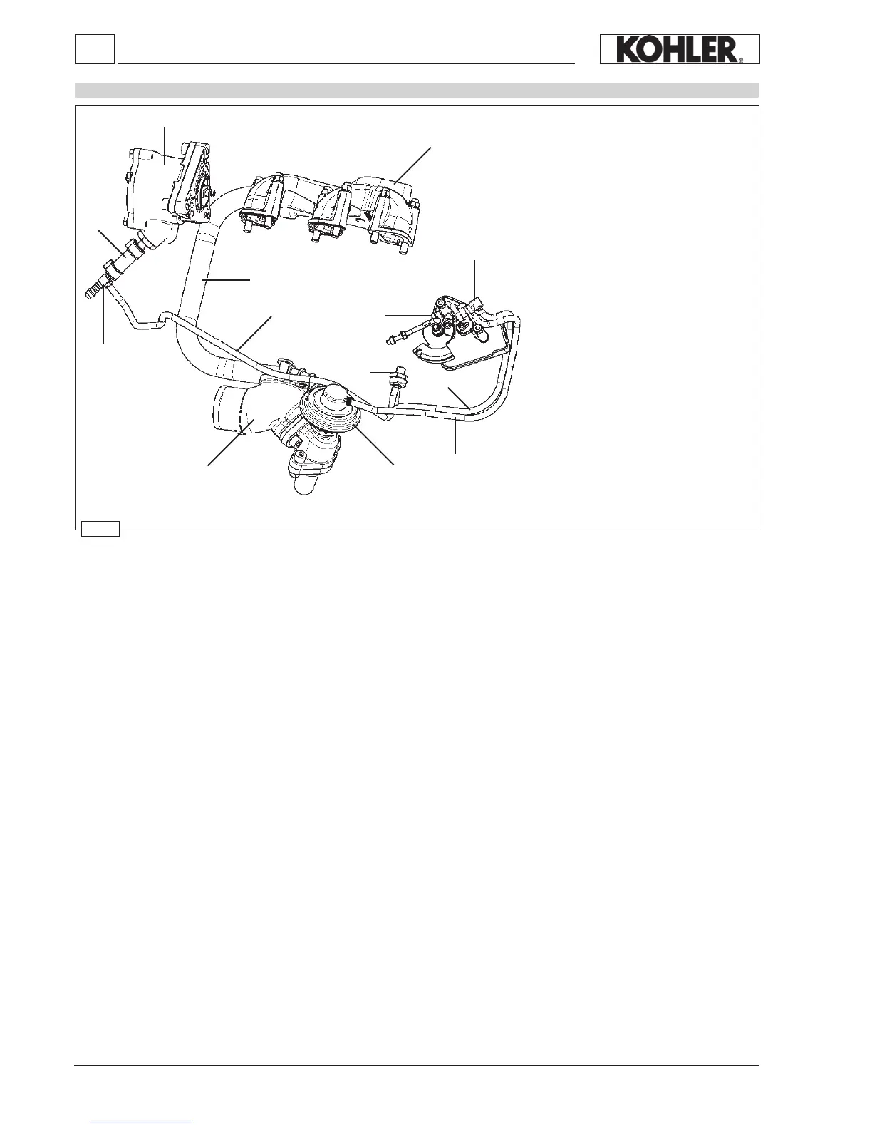
Components:
1. Exhaust manifold
2. E.G.R. Pipe
3. E.G.R. Valve
4. Vacuum pump
5. Three way union
6. Vacuum pump pipe
7. Thermovalve – vacuum pump con-
nection pipe
8.
Vacuum valve – thermovalve con-
nection pipe
9. Vacuum valve - E.G.R. connection
pipe
10.
Thermovalve
11. Vacuum valve
12. ON-OFF sensor control cam
13. Intake duct
E.G.R. Circuit
Disassembly / Reassembly
Operation
The main function of the E.G.R. (Exhaust Gas Recirculation) system is the reduction in emission of NOx (nitrogen oxides),
gases harmful to people and the environment, via lowering the combustion temperature.
The system takes a certain quantity of exhaust gas from the exhaust manifold 1 via the E.G.R. pipe 2 to the E.G.R. valve 3.
This valve is opened by the vacuum (created in pipes 6, 7, 8 and 9 by vacuum pump 4) only when:
a) thermovalve 10 placed in contact with the engine refrigerant uid reaches a temperature of 40 °C;
b) the on-off sensor control cam 12 opens the vacuum valve 11 at a determined accelerator position.
Once the E.G.R. valve is opened, the exhaust gas enters the intake manifold 13 via the intake ange.
The same logic controls the closure of the E.G.R. valve.
 Loading...