- 84 -
KD 702_1003_1404 Workshop Manual_cod. ED0053029340_1° ed_ rev. 00
164
165
166
167
10
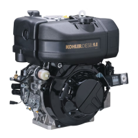
Fuel feeding / injection circuit
Components: 1 Fuel Tank
2 Fuel lter
3 Fuel feeding tube
4 Fuel lift pump
5 lnjection pump
6 Injector
7 Fuel rail passage rubber joint
8 Injector exhaust pipe
9 Fuel tank cap
10 Solenoid valve
Note: The tank complete with lter is supplied on request.
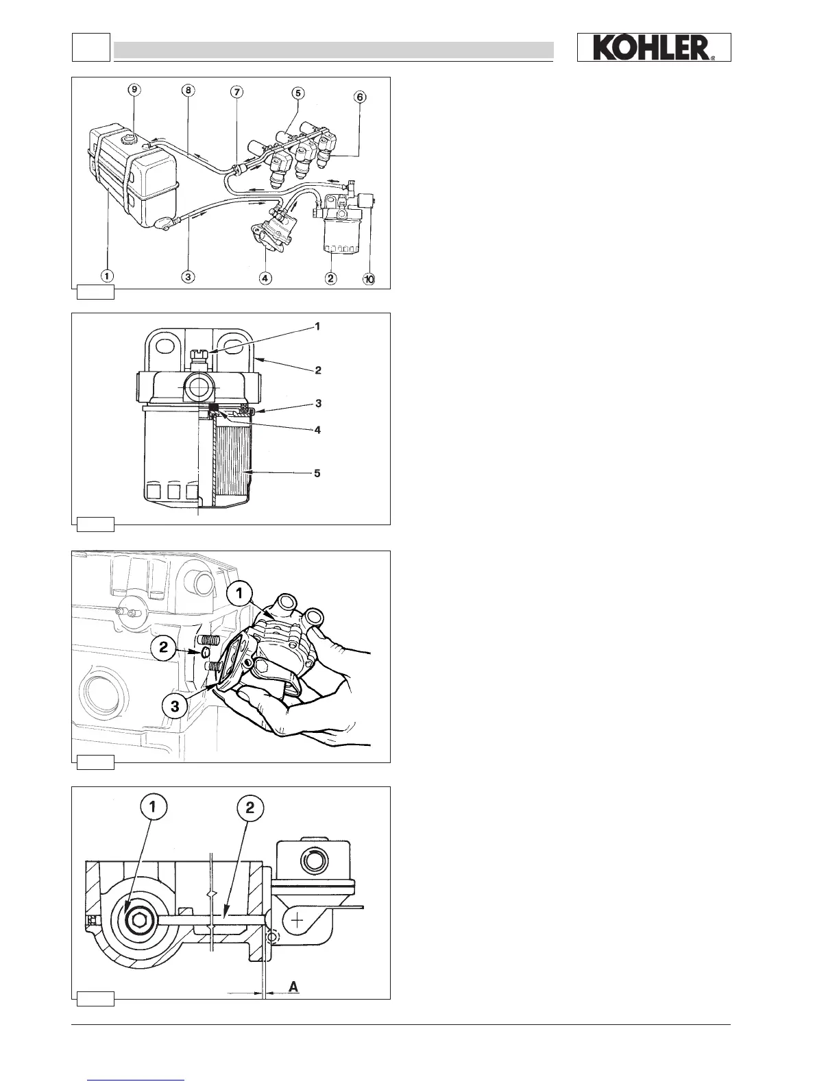
Fuel pump drive rod projection
The protrusion A of drive rod 2 from the cylinder head surface is
1.66÷2.18 mm.
The check must be carried out with cam 1 idle as in the gure.
Block the two fuel pump fastening nuts simultaneously at 24
Nm.
Check the length of the drive rod and if it is not the right size,
replace it.
Drive rod length = 153.15÷153.35 mm.
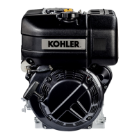
Fuel lift pump
Components:
1 Fuel lift pump
2 Push rod
3 Seal ring
The fuel pump is membrane type. It is driven by camshaft cam
via a drive rod.
It is equipped with an external manual fuel lever.
Characteristics:
With the control cam at 1500 rpm the delivery rate is 75 l/hours
and the self-adjusting pressure is at 0.55 to 0.65 bar.
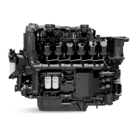
Fuel lter detached from the tank (on request)
1 Air relief valve
2 Bearing
3 Cartridge
4 Rubber element
5 Filtering element
Cartridge characteristics:
Filtering paper:.................................. PF 905
Filtering surface:
............................... 2400 cm
2
Degree of ltration: ........................... 2÷3 µ
Maximum operating pressure: .......... 4 bar
See page 32 for periodic maintenance details.
FUEL SYSTEM
 Loading...