- 69 -
KD 702_1003_1404 Workshop Manual_cod. ED0053029340_1° ed_
6
125
124
120
122
121
123
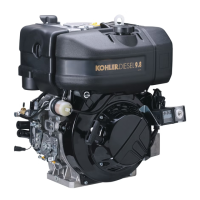
Connecting rod alignment
Use of a size corresponding with the surface plate or as a com-
parator in the gure.
Check the alignment of the axes using the piston pin, the gap A
= 0.015 mm. Limit 0.030 mm.
Small deformations can be corrected in a press acting with gra-
dual efforts.
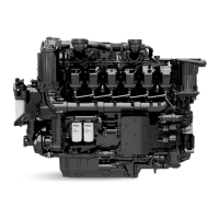
CYLINDERS
Reset the dial gauge with a calibrated ring: check the diameter
D in points 1, 2 and 3; repeat the same operation rotating the
dial gauge by 90° at the same heights.
Check any wear in zone X where the piston rings operate and if
it is greater than the 0.05 mm max limit given adjust the cylinder
to the next increased value.
75,000 mm for KDW 702-1003-1404 engines.
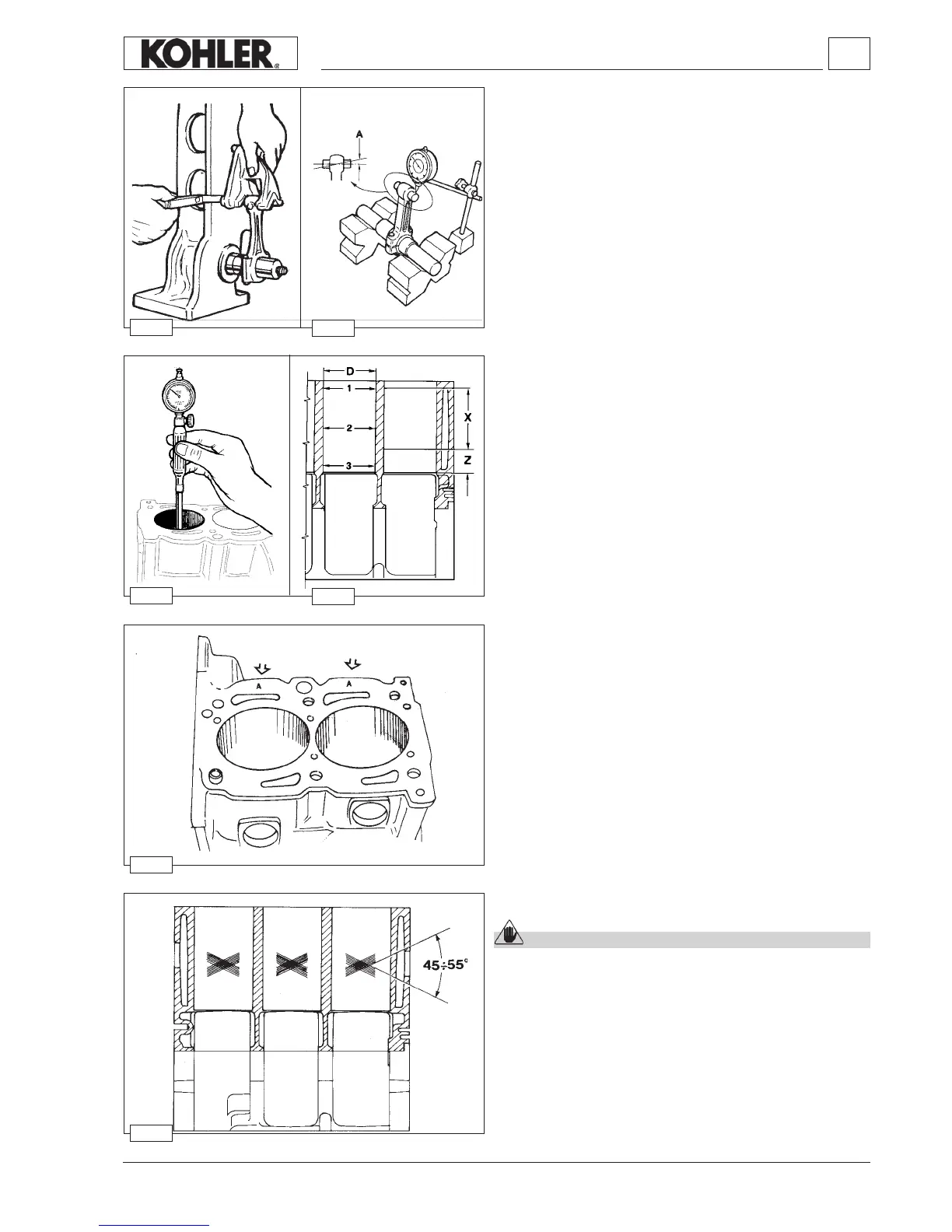
Cylinder roughness
Caution – Warning
Do not treat the cylinder’s internal surfaces with an emery
cloth.
The angle of the crossed processing marks must be between
45° and 55°. These must be uniform and distinct in both
directions.
Average roughness must be between 0.5 and 1 µm.
The whole surface of the cylinder affected by contact with the
piston rings must be rendered with the plateau method.
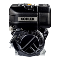
Cylinder, class
The pistons (A, B, C) locations are shown on the piston crown
while those for the cylinders are found on the crankcase in the
points shown by the arrows, see picture.
Note:
The cylinders are not to be changed.
Disassembly / Reassembly
 Loading...