- 89 -
KD 702_1003_1404 Workshop Manual_cod. ED0053029340_1° ed_
10
181
179
177
178
180
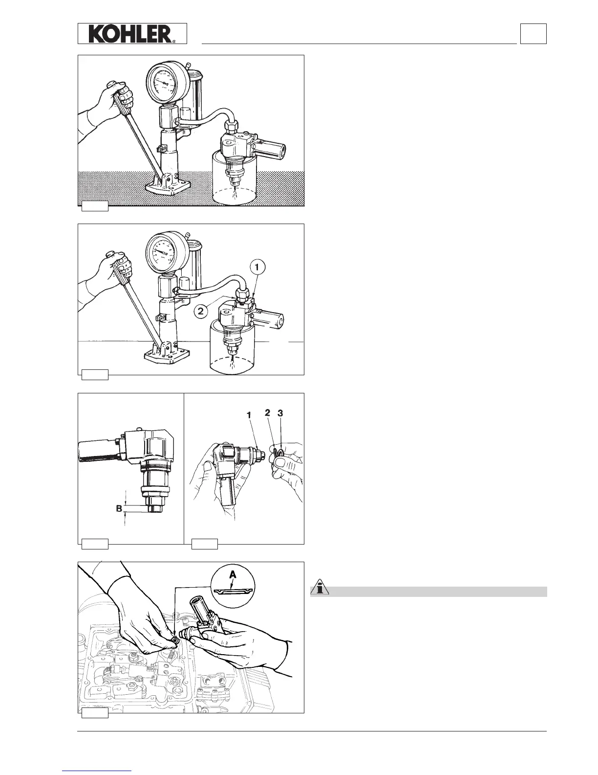
Injector, setting (old type)
Connect the injector to a hand pump after removing cap screw
(20 g. 169).
By means of the tool - se.no. 7107-1460-028 - check that the
setting pressure is 130÷145 bar.
Adjust, if necessary, by changing the spacer located under the
spring.
There are eleven different spare part spacers from 1 to 2 mm.
When you replace the spring, the setting should be made at a
pressure higher than 10 bar to compensate for adjustments in
operation.
Check the needle seal by slowly actuating the hand pump for 10
seconds, until you reach abt. 130 bar.
If the nozzle drips, replace it.
Injector, spark arrester
Important
Every time you remove the pump/injector you must replace
the spark arrester, the copper gasket, the oil O-ring, as well
as the 2 fuel O-rings.
Insert the spark arrester in the injector housing with surface A
pointing upwards.
Tighten simultaneously both nuts that fasten it to the head at
20 Nm.
For engines with the injectors xed with self-locking nuts,
tighten the nuts at 23 Nm.
See page 32 for periodic maintenance details.
Injector, nozzle projection
To avoid excessive compression of the spark arrester (A, g.
181), check projection B of the nozzle (g. 179).
B = 6.80÷7.05 mm.
If this measure is larger put spacer 2 between ring nut 1 and
copper gasket 3.
0.25 mm thick spacers are available.
Setting of injector according to current pump/injector unit
Remove the non-return valve leaving its metal gasket and t a
cap screw in its place, that is part of tooling 7107-1460-074.
Mount then head 1 and coupling 2.
Then connect a hand pump as shown in the picture.
The pressure setting must be 140÷155 mm bar.
Fuel system
 Loading...