- 54 -
KD 702_1003_1404 Workshop Manual_cod. ED0053029340_1° ed_ rev. 00
6
64
62
59
60
63
61
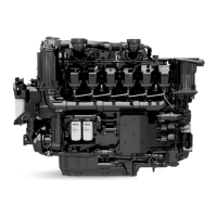
Valve / Rocker arm clearance
Important
Setting should be performed when the engine is cold.
Bring each cylinder piston to top dead center on the
compression stroke and set clearance A at 0,20 mm for both the
intake and exhaust valves.
For greater convenience, clearance check B is accepted. In this
case the value is 0.15 mm.
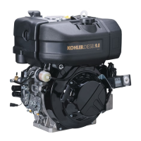
Crankcase breather
For KDW 702-1003-1404 engines, the exhaust gases exit from
the cylinder head cover (see Fig. 53, 54).
Remove the cover, check the integrity of the air valve and oil
decanting wire gauze.
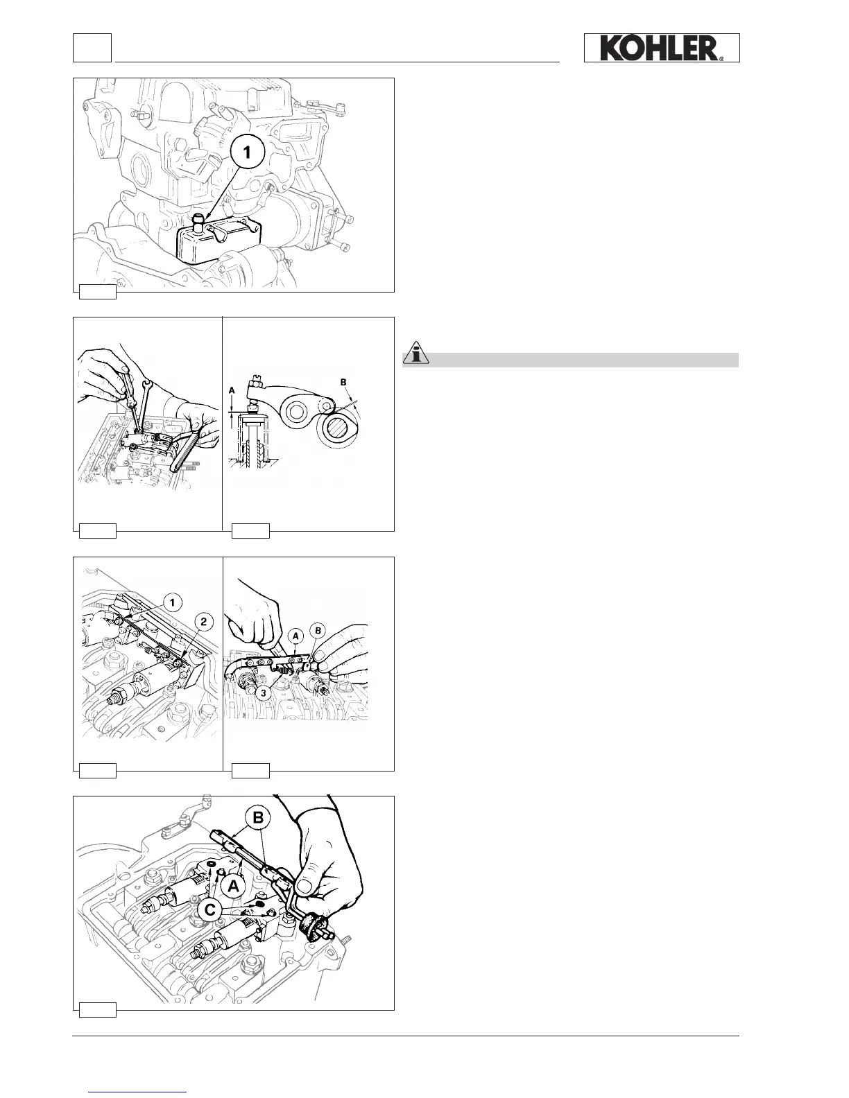
Fuel rail
When removing the fuel feeding pumps A, with the rail holders
B, pay attention that the sealing O-rings C remain in their seats.
When retting tighten the rail holder screws at a torque of 4
Nm.
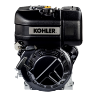
Injection pump control rod
Depending on the engine model, the injection pump control rod
will link two, three, or four injectors to the engine governor.
Screws 1 and 2 are pivoted on the delivery control lever of each
pump/injector B, unscrew the screws and remove spring 3.
When retting tighten the screws 1 and 2 at a torque of 1,1 Nm
and make sure that they stop on lever B of each pump/injector
and not on rod A.
To carry out the delivery equalisation of the injection pumps
see page 93.
To carry out the timing of the injection pumps and speed
governor see page 105
Disassembly / Reassembly
 Loading...