Repair manual KTM LC4
7-4E
Art Nr 320549-D
Checking the voltage regulator-rectifier
– Start the engine and switch on the low beam.
– Connect a voltmeter to the two terminals of the capacitor (red/white
cable = positive, brown cable = negative).
– Accelerate the engine to a speed of 5000 r.p.m. and read off the
voltage.
Nominal value: 14.0 - 15.0 V
If the reading significantly deviates from the nominal value above,
check the capacitor. If the capacitor is intact, replace the voltage
regulator-rectifier.
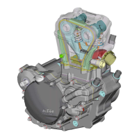
Checking the voltage regulator
The two voltage regulators are located under the right side cover at the
air filter box.
The voltage regulators are connected downstream of the switches. One
of the voltage regulators regulates only the brake light circuit, the other
regulates the circuit for the head light, the tail light, the speedometer
illumination and the horn.
A defect voltage regulator can cause different kinds of trouble:
● No voltage in the circuit
In this case, the voltage regulator must be disconnected at idle speed.
The voltage regulator is defect if the power consumers now work
properly.
If the power consumers are still not supplied with power, the switch, the
wiring harness or the ignition system must be checked for defects.
● Excessive voltage in the circuit
The bulbs burn out.
Connect a voltmeter (yellow cable = positive, brown cable = negative)
to check the voltage. Start the engine and switch on the power
consumers.
At an engine speed of 3000 r.p.m, the voltage regulator must supply a
voltage of 12.0 - 14.0 V A.C. At higher engine speeds, the limit of 14 V
should not be exceeded either.
If the reading significantly deviates from the nominal value, replace the
voltage regulator.
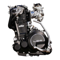
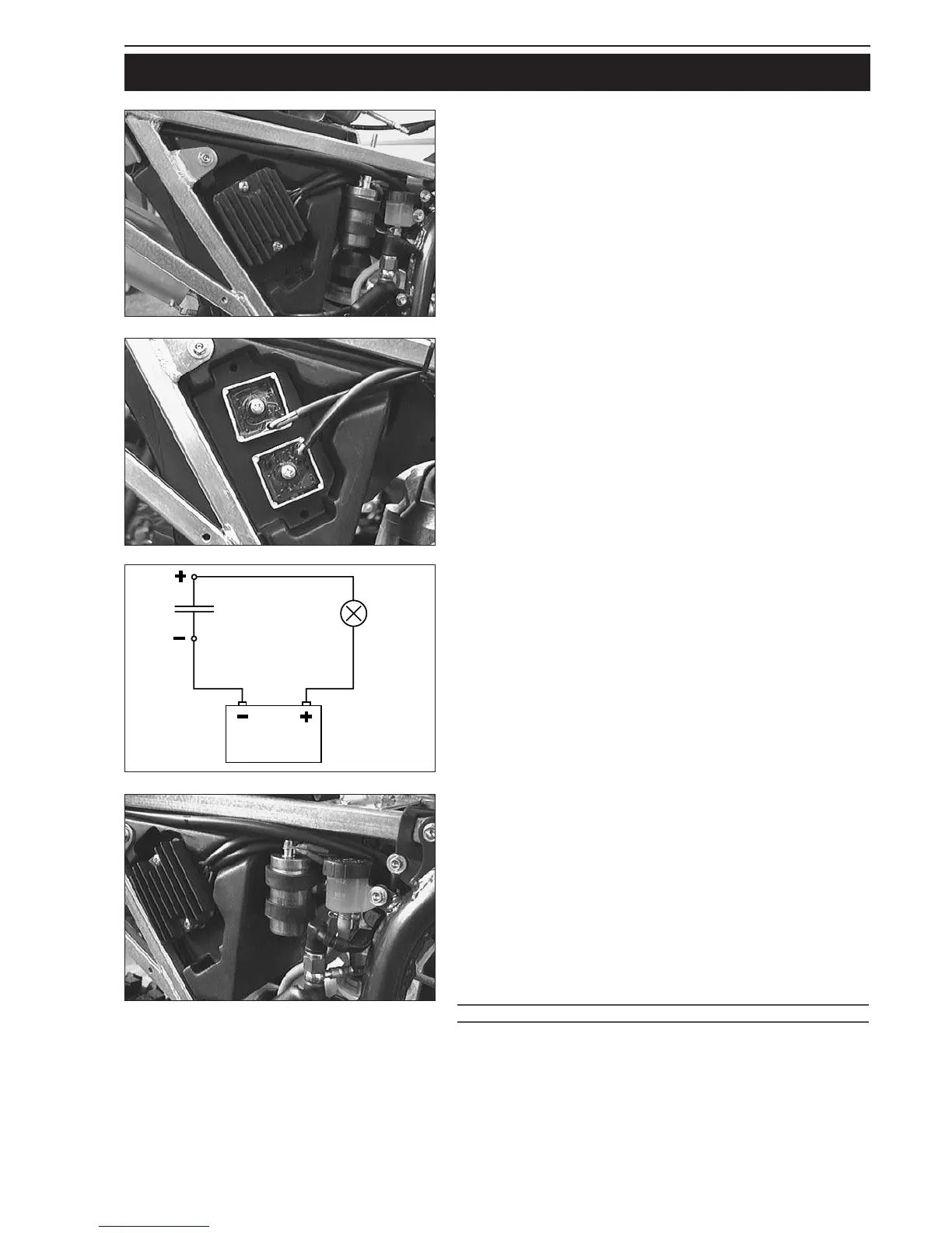
Checking the capacitor
– Discharge the capacitor 1 by bridging the two terminals with a
screwdriver and remove.
– Connect the negative pole of a 12V battery with the negative
terminal of the capacitor. The connection between the positive pole
of the battery and the positive terminal of the capacitor (marked +)
is made with a test lamp
1.
– When the power circuit is closed, the test lamp must begin to light
up. As capacitor charging increases, the brightness of the test lamp
must decrease.
– The test lamp must go out after 0,5-2 seconds (depending on the
lamp capacity).
– If the test lamp does not go out or does not light up at all, the
capacitor is faulty.
!
CAUTION
!
DISCHARGE THE CAPACITOR BEFORE AND AFTER EACH TEST.
W
HEN INSTALLING THE CAPACITOR, MAKE SURE THAT THE TERMINALS ARE
CONNECTED IN ACCORDANCE WITH THEIR MARKINGS
. CONNECT RED/WHITE CABLE
TO
+ TERMINAL.
1
ELECTRICAL – SUPER COMPETITION
 Loading...