Repair manual KTM LC4 Art.-Nr. 3.206.014 -E
7-44E
1
3
4
5
S
NOTE: Before performing a test with the peak voltage adapter, make
sure that the orange cable (battery voltage) is applied to the CDI unit
and the black and white/black cables are applied to the ground.
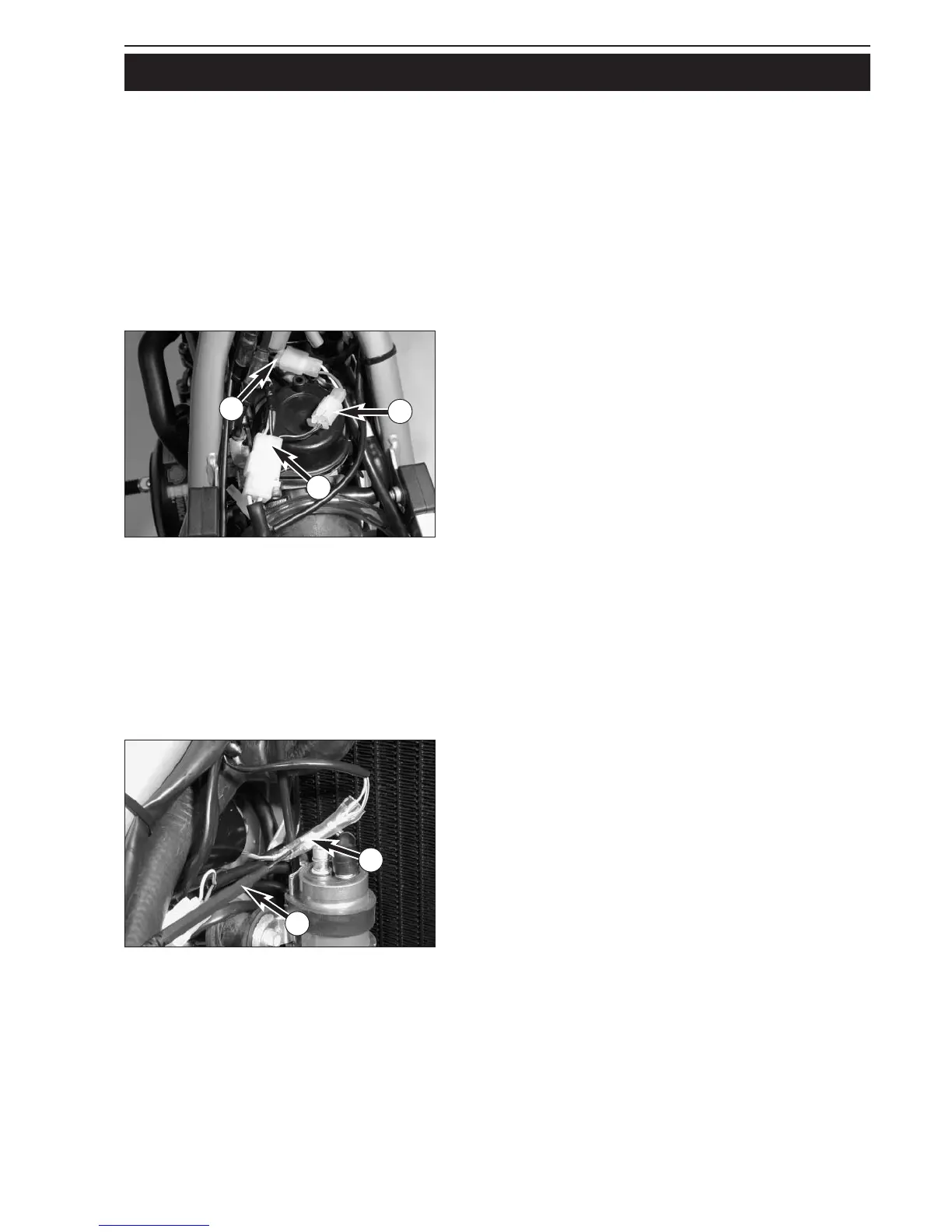
Check the pulse generator for an output signal – two-pin connector
1
with green and white cable colors (also see circuit diagram on opposite
page):
– Apply the red measuring lead of the peak voltage adapter to the
green cable and the black measuring lead to the white cable,
disconnect connector
1 to disconnect the CDI unit 2.
Multimeter display: 7 volts +/- 1 volt
– Same measurement with CDI unit connected
Multimeter display: 4 volts +/- 1 volt
Check the generator phase for detection of the direction of rotation
three-pin connector
3 with red/black and black/yellow cables (also see
circuit diagram on opposite page):
– Apply the red measuring lead of the peak voltage adapter to the
red/black cable and the black measuring lead to the black/yellow
cable, disconnect connectors
3 and 4
Multimeter display: 17 volts +/- 1 volt
– Same measurement with connectors
3 and 4 connected
Multimeter display: 12.5 volts +/- 0.5 volt
Check the primary voltage output for ignition coil control for output
voltage – one-pin connector
5 with blue/white cable (also see circuit
diagram on opposite page):
– Apply the red measuring lead of the peak voltage adapter to the
ground and the black measuring lead
S to the blue/white cable, CDI
unit
2 and ignition coil 6 connected
Multimeter display: 220 volts +/- 10 volts
STATIC IGNITION VALUES 400/640 LC4-E / 625 SXC (KOKUSAN 4K-2)
Measuring conditions:
– cold engine
– seat, side trim and tank removed
– all connectors and the ground connection in a non-corroding condition, connectors tightly connected
– battery loaded, ignition switch to position 1 (without light)
– the gap between the rotor and pulse generator must be set to 0.75 mm
– compression release lever pulled
– kick the kick starter forcefully at least 5 times for each measurement
 Loading...