EasyManua.ls Logo

KTM 400-660 LC4 1998-2005 User Manual

KTM 400-660 LC4 1998-2005
501 pages
To Next Page IconTo Next Page
To Previous Page IconTo Previous Page
Page #126 background imageLoading...
Page #126 background image
7-15E
G
M
Ignition system
From the battery 1, battery voltage is delivered via the main fuse 2,
through the activated ignition lock
3 and the activated emergency OFF
switch
4 to the CDI unit 6.
During each revolution of the crankshaft, the pulse generator
7
supplies a signal to the CDI unit 6. In the CDI unit, this signal is
processed so as to calculate the ignition point.
This ignition pulse is passed on to the ignition coil
8 (the ignition spark
is produced).
The ignition system is a digital high voltage capacitor ignition that
receives its power supply from the battery. Therefore, it works only with
an intact battery.
When the battery is discharged below the threshold level, the voltage
can, due to the starting process, drop below the minimum supply
voltage required by the ignition. In this case, turn off the light, and use
the kickstarter.
!
CAUTION
!
S
AFE AND FAULTLESS OPERATION OF THE DIGITAL IGNITION REQUIRES SPARK PLUG
CONNECTORS AND SPARK PLUGS WITH INTEGRATED RESISTANCE TYPE SUPPRESSORS
.
bl . . . . . . . . .blue
br . . . . . . . . .brown
ge . . . . . . . .yellow
gr . . . . . . . . .grey
g . . . . . . . . .green
o . . . . . . . . .orange
r . . . . . . . . . .red
ra . . . . . . . . .pink
s . . . . . . . . . .black
v . . . . . . . . .violet
w . . . . . . . . .white
1
2
3
4
6
to EPC-control-
unit
7
8
1
Battery
2
Main fuse (20 A)
3
Ignition lock
4
Emergency-off switch
5
Auxiliary relay
6
CDI
7
Pulse generator
8
Ignition coil
s-r
r-s
bl-w
s
w
g

Table of Contents

Question and Answer IconNeed help?

Do you have a question about the KTM 400-660 LC4 1998-2005 and is the answer not in the manual?

KTM 400-660 LC4 1998-2005 Specifications

General IconGeneral
BrandKTM
Model400-660 LC4 1998-2005
CategoryEngine
LanguageEnglish

Summary

REMOVING AND REFITTING ENGINE

REMOVING THE ENGINE

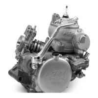
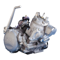
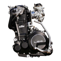
Detailed steps for safely removing the engine from the motorcycle frame.

REFITTING THE ENGINE

Detailed steps for correctly reinstalling the engine into the motorcycle frame.

DISASSEMBLING THE ENGINE

REMOVING THE CYLINDER HEAD

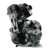
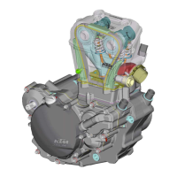
Steps for removing the cylinder head assembly from the engine.

PARTING OF ENGINE HOUSING

Instructions for separating the engine crankcase halves.

SERVICING ON INDIVIDUAL COMPONENTS

CRANKSHAFT

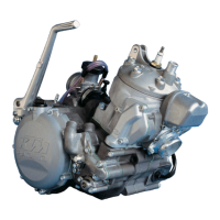
Technical specifications and checks for the crankshaft.

DISASSEMBLING THE CAMSHAFT AND CHECKING THE COMPONENTS FOR WEAR

Steps to disassemble the camshaft and inspect its components for wear.

ASSEMBLING THE ENGINE

ELECTRICAL

FUEL SYSTEM

TROUBLE SHOOTING

TROUBLE SHOOTING (SX, SXC, SC, SMC)

Common issues and solutions for SX, SXC, SC, and SMC models.

TROUBLE SHOOTING (LC4 COMPETITION)

Common issues and solutions for LC4 Competition models.

TROUBLE SHOOTING (LC4)

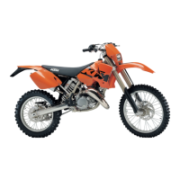
Common issues and solutions for LC4 models.

CHASSIS

TIGHTENING TORQUE

ENGINE

Specific torque values for engine assembly bolts and nuts.

CHASSIS

Specific torque values for chassis assembly bolts and nuts.

PERIODIC MAINTENANCE SCHEDULE

VITAL CHECKS AND CARE PROCEDURES TO BE CONDUCTED BY THE OWNER OR THE MECHANIC

WIRING DIAGRAMS

DETAIL WIRING DIAGRAMS

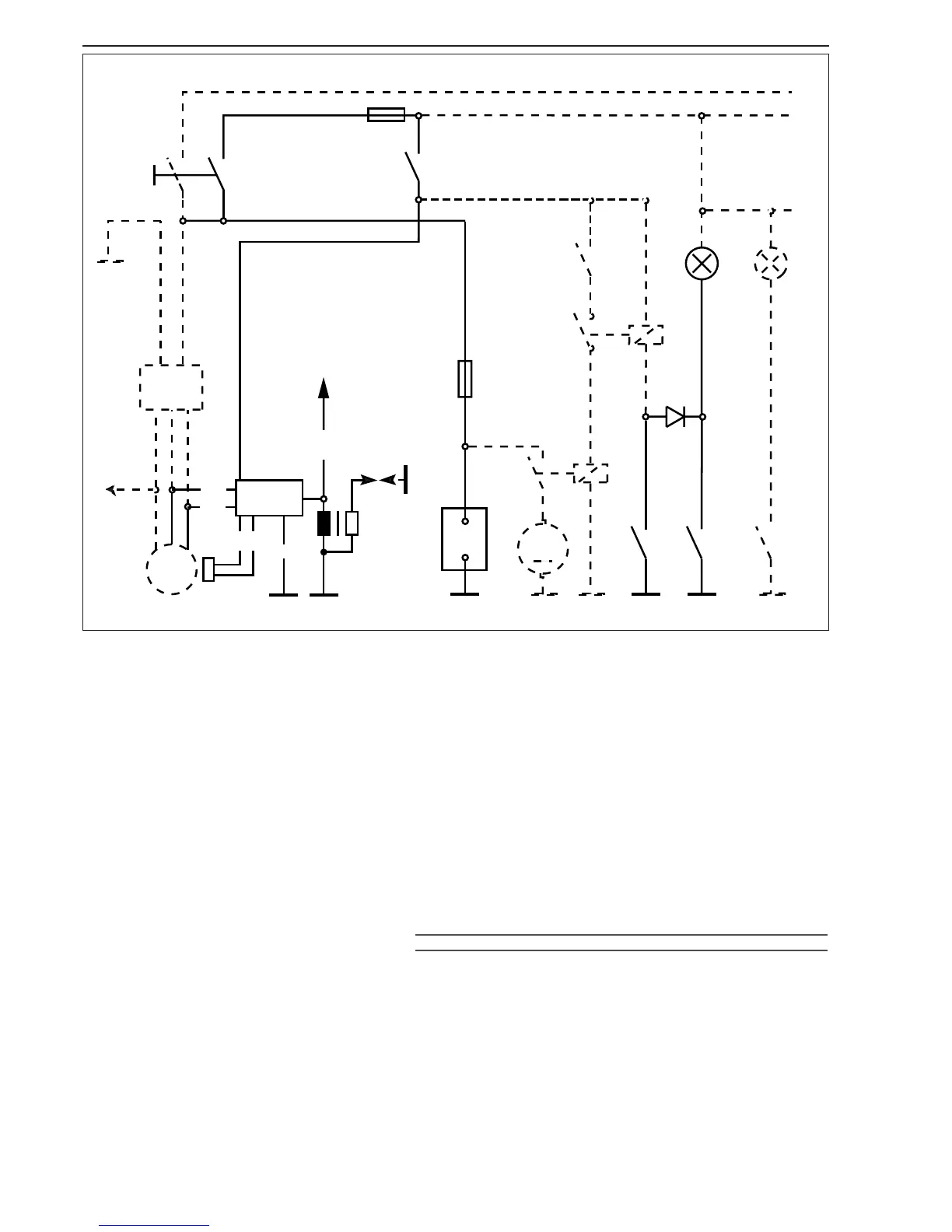
Detailed wiring diagrams for various models and systems.

Related product manuals