7-25E
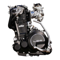
Checking the diodes
NOTE: Diodes conduct current only in the direction indicated by the
arrow, preventing the conduction of current in the opposite direction.
Two different kinds of diode defects can be distinguished:
– The diode conducts no current at all.
– The diode conducts current in both directions.
Diode defects can lead to different kinds of trouble, depending on the
type of defect.
NOTE: Both diodes are the same type and require the same testing
procedure. They are each located in a 2-pole connector and can be
identified by the color of the cables leading up to and away from the
respective connector.
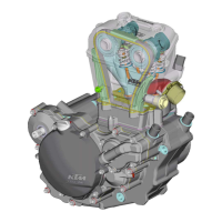
Checking the diodes for faultless operation:
– Remove the headlight mask.
– Pull the diode to be tested out of the connector.
– Connect an appropriate ohmmeter to the diode and check for
continuity.
– Connect the ohmmeter in the opposite direction and check if the
diode prevents current conduction in the opposite direction.
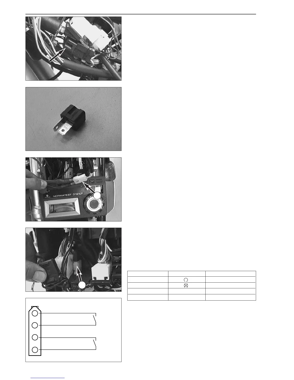
Checking the clutch switch
–Disconnect the clutch switch from the cable tree.
– Connect the ohmmeter to the 2-pole connector
3 (cable colors:
yellow/yellow) of the clutch switch and slowly pull the clutch lever.
– The switch must connect when the lever is pulled approximately half
of the overall distance.
Checking the tip switch and the emergency off switch
– Remove the headlight mask.
– Disconnect the 4-pole connector
4 of the tip switch/emergency OFF
switch from the cable tree.
– Use an ohmmeter and test both switches according to the table
below (please refer to the sketch for the configuration of the
connector).
– Then check all lines for ground contact.
starter
tip
switch
emergenc
y off
switch
3
4
Circuit Position Condition
Emergency off switch duct
Emergency off switch no duct
Tip switch operated duct
Tip switch not operated no duct
 Loading...