GV 640 Service Manual 53
For internal use only
6.7 Heater pump
The heater pump comprises a heater, temperature sensors and a circulation pump in a casing.
6.7.1 Structure of the heater pump
1 Pressure joint
2 Circulation pump motor
3 Circulation pump motor connection
4 Heater connection
5 Casing cover
6 Intake socket
6.7.2 Structure of the pump casing
1 Pump casing with an integrated temperature
shield made of metal
2 Heating tube with NTCs
3 BLDC motor
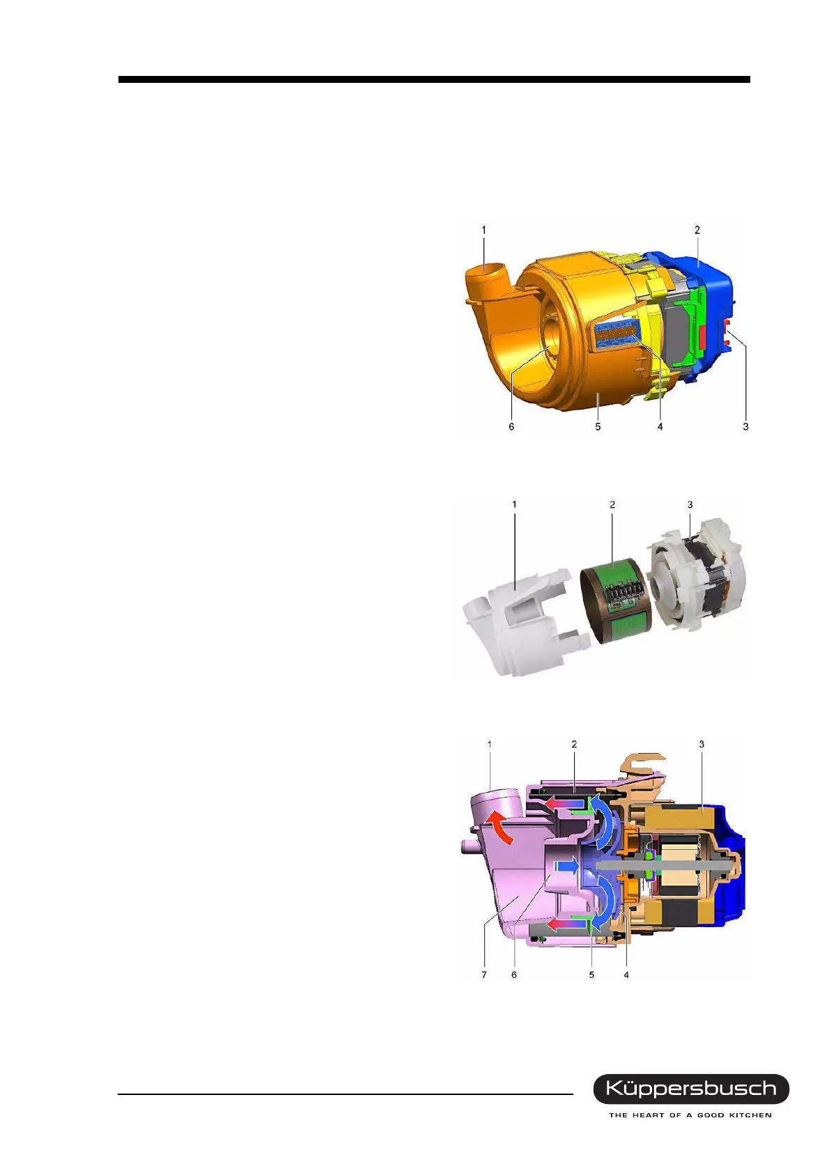
6.7.3 Structure of the circulation pump
1 Pressure joint
2 Heating tube with NTCs
3 BLDC motor
4 Pump wheel
5 Guiding wheel
6 Intake socket
7 Pump housing with air intake and pressure
joint
 Loading...