60 GV 640 Service Manual
For internal use only
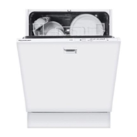
The new fine filter system is based on a corrugated
fine filter system.
When this filter is unrolled, a 1.5-fold filtering sur-
face is shown.
1 Corrugated fine sieve cylinder, rolled
2 Fine sieve cylinder, unrolled
3 Fine sieve cylinder, unrolled
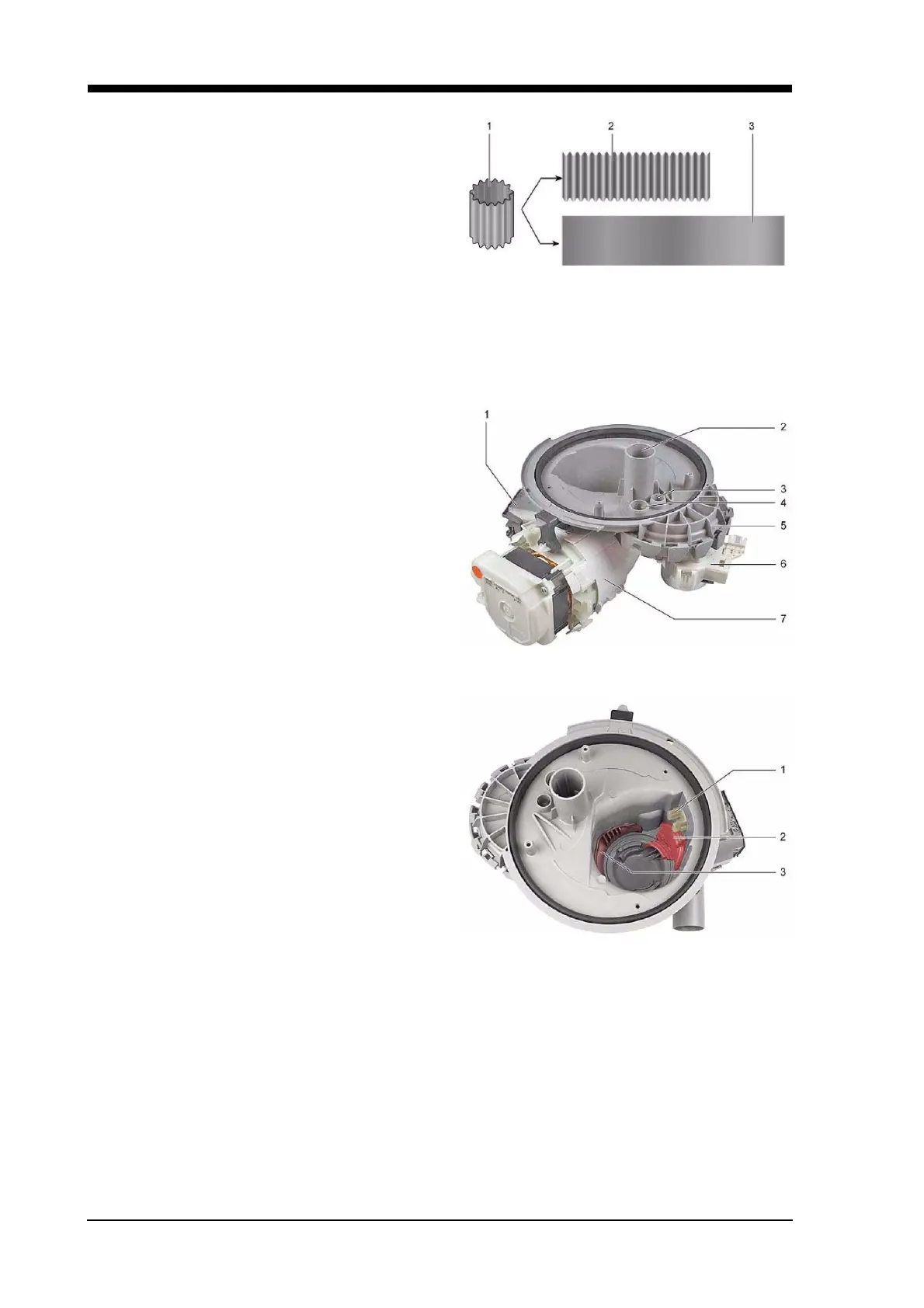
6.10 Pump cavity
This shows the pump cavity and all the attach-
ments.
1 Discharge pump
2 Lower spray arm connection
3 Ceiling centrifugal arm water intake pipe
connection
4 Top spray arm intake pipe connection
5 Water diverter
6 Water diverter motor with a pulse generator
7 Heater pump
1 Aqua sensor
2 Discharge pump cover
3 Intake cover
A non-return valve has been fitted into the hose
connection of the pump cavity. This prevents dirty
water from flowing back into the pump cavity.
Covers in the pump cavity
The intake cover ensures optimal intake and flow properties of the pump. No air and no dirt are taken in.
This cover should not be removed by the customer.
The cover of the discharge pump serves to channel the water. The discharge pump would not be able
to build up pressure without the cover. Customers can remove the cover of the discharge pump for clean-
ing purposes. The pump will not operate if it is not properly engaged.
 Loading...