74 GV 640 Service Manual
For internal use only
Assembly
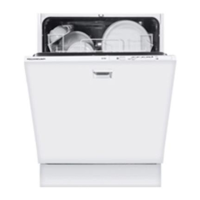
1. Carefully move the ribbon cable to behind
the hinge plate.
2. Restore the plug connection.
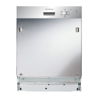
3. Lock the LEDs and the Hall sensor into
place in the frame of the rinsing cavity.
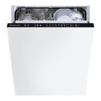
7.9 Flow sensor
7.9.1 Functioning
The flow sensor (impeller metre) is installed in the
water channel of the heat exchanger. The impeller
is turned when water flows through the channel.
A small permanent magnet installed on the impel-
ler activates the two solenoid-operated switch con-
tacts (reed switch). This results in electric pulses.
These pulses are counted by the electronics unit.
The electronics unit uses the pulses to calculate
the amount of water that flows into the dishwasher.
1 Circuit board with a reed contact switch
2 Permanent magnet
3 Impeller wheel
2
 Loading...