Wiring the standard device
Basic devices in the power range 75 ... 90 kW
Motor connection
5
5.7
5.7.4
5.7-8
EDSVF9333V EN 3.0-06/2005
Features of the connection for motor temperature monitoring:
Pin X8/5, X8/8 from incremental encoder input (X8)
Connection Linear KTY thermal sensor
Tripping point z Warning: Adjustable
z Error (TRIP): Fixed at 150 °C
Notes z Monitoring is not active in the Lenze setting.
z The KTY thermal sensor is monitored with regard to interruption
and short circuit.
T1
T2
PE
U
VW
2
3
4
0
M4 x 12: 2.5 Nm (22.1 lb-in)
M5 x 12: 3 Nm (26.5 lb-in)
U, V, W,
PE
M10
30 Nm
264 lb-in
1
a
}
+
PE
9300vec125
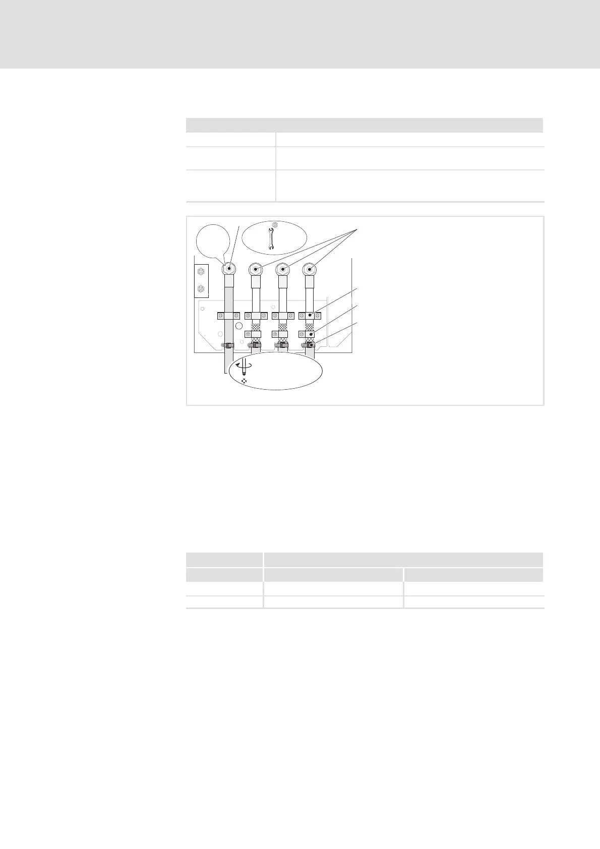
Fig. 5.7-6 Motor connection with KTY thermal sensor
PE stud
Connection of PE cable
U, V, W
Connection of motor cable with ring cable lugs
Observe correct polarisation. Observe maximum length of motor cable.
Cable clamps for strain relief of motor cable
FastencableclampswithM4×12mmscrews
Shield clamps
Place shields of motor cable with large surface on the shield sheet and
fastenwithshieldclampsandM5×12mmscrews
Cable ties for additional strain relief of motor cable
9300 vector Cablecross-sectionsU,V,W,PE
Type [mm
2
] [AWG]
EVF9332 95 3/0
EVF9333 120 4/0
Cable cross-sections
 Loading...