Wiring the standard device
Control connections
Without ”safe standstill” function
5
5.9
5.9.3
5.9-6
EDSVF9333V EN 3.0-06/2005
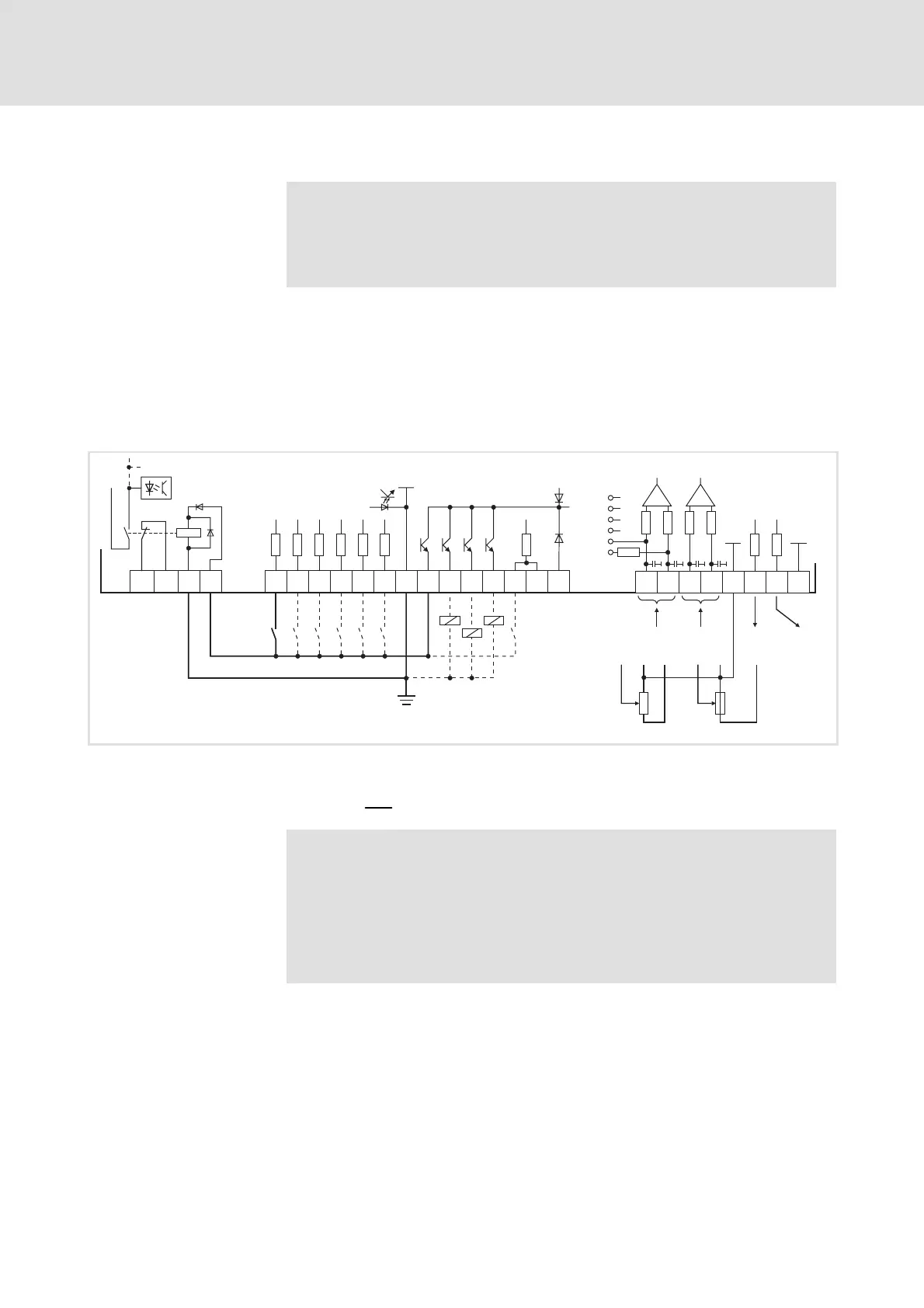
5.9.3 Without ”safe standstill” function
Note!
If you do not use the ”safe standstill” function, the safety relay
K
SR
must permanently carry a current, so that the drivers of the
power output stage are supplied with voltage.
ƒ For supplying the digital inputs (X5/E1 ... X5/E5, X5/ST1), a freely
assignable digital output (e. g. X5/A1) must be firmly applied to HIGH
level.
ƒ For supplying the analog inputs (X6/1, X6/2 and X6/3, X6/4), a freely
assignable analog output (e. g. X6/63) must be firmly applied to HIGH
level.
GND2 +24V+5 V
E5
A2 A3 A4 ST1
ST2
59
39
3k
47k
50mA
50mA
50mA
50mA
X5
28
E1 E2 E3 E4
3k
3k
3k
3k
3k
X11
K31K32 33 34
S1
+
K
SR
A1
X3
X6
1
AIN1 AIN2
2
3
4
AOUTx
1
3
2
10k
242R
1
2
3
4
5
6
100k
100k
100k
100k
3.3nF
GND1 GND1
AOUT1 AOUT2
AOUTx
4
10k
7762
63
9300vec0137
Fig. 5.9-4 Wiring of digital and analog inputs/outputs without ”safe standstill” function
with internal voltage source
S1 Enable controller
The min. wiring requirements for operation
Note!
If you load a basic configuration C0005 = xx1x (e.g. 1010 for
speed control with control via terminals), the following terminals
areswitchedtoafixedsignallevel:
ƒ Terminal X5/A1 to FIXED1 (corresponds to DC 24 V).
ƒ Terminal X6/63 to FIXED100% (corresponds to 10 V).
Supply via internal voltage
source
 Loading...