Commissioning
Changing the assignment of the control terminals X5 and X6
Free configuration of digital input signals
6
6.5
6.5.1
6.5-2
EDSVF9333V EN 3.0-06/2005
The internal digital signal can be linked with an external signal source by
entering the selection figure of the external signal into the configuration
code of the internal digital signal.
Example
ƒ C0787/2 =53 Ösignal source for JOG2 is terminal X5/E3
E1
E2
E3
E4
E5
1
0
C0114/1...6
DIGIN
DIGIN1
DIGIN2
DIGIN3
DIGIN4
DIGIN5
28
DCTRL -X5/28
X5
DIGIN-CINH
1
1
ST
DIGIN6
C0443
NSET
C0046
NSET-N
DMUX
0
3
0
15
NSET-JOG*1
NSET-JOG*2
NSET-JOG*4
NSET-JOG*8
JOG1...15
C0780
C0787/1
C0787/2
C0787/3
C0787/4
9300vec105
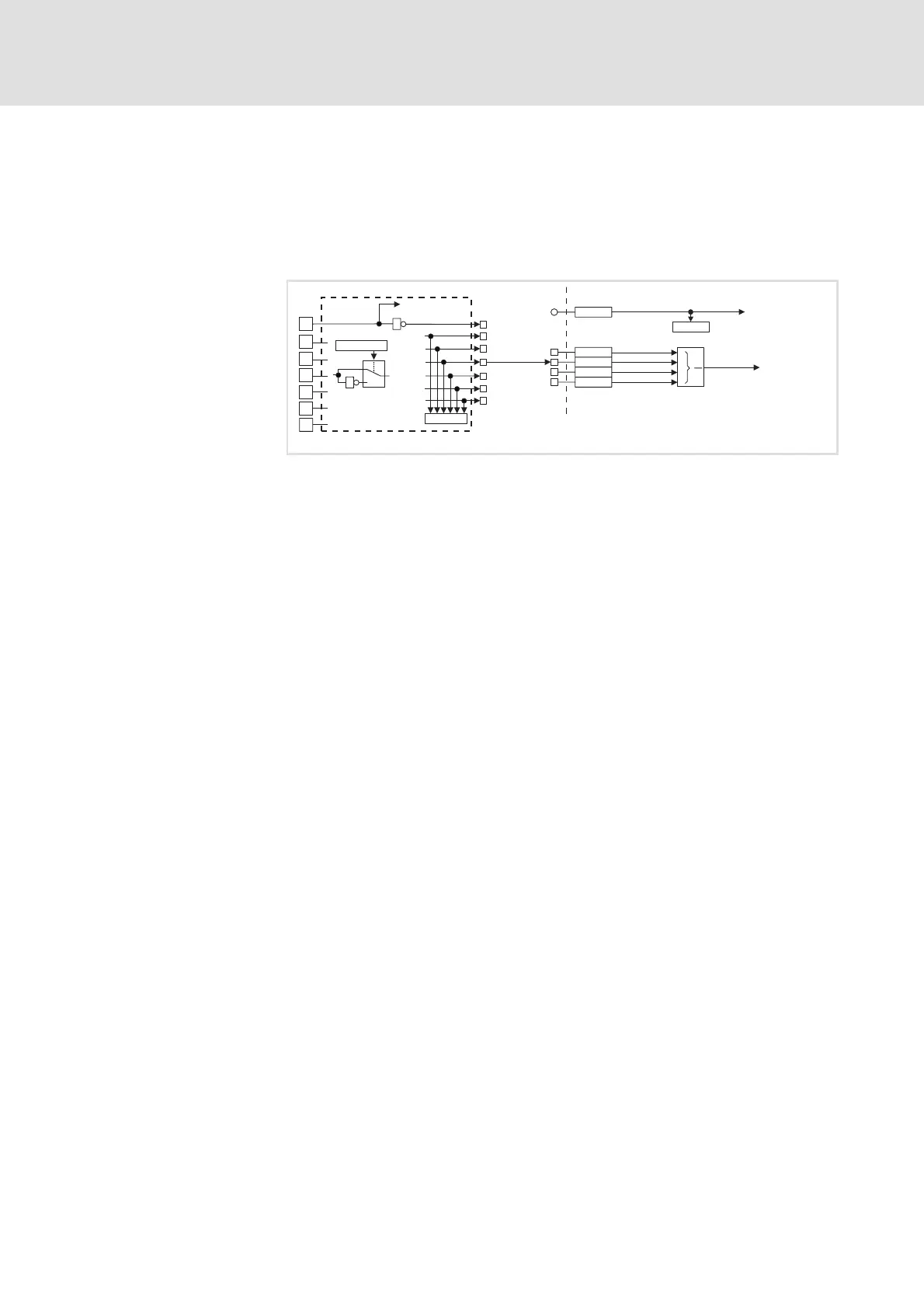
Fig. 6.5-1 Connecting digital signal JOG2 with terminal X5/E3
Tip!
ƒ A list with all selection digits is included in the chapter
”Configuration” → ”Selection lists”.
ƒ For signal linkage we recommend the function block editor in
GDC (ESP-GDC2).
ƒ Terminals (X5/E1 ... X5/E5):
– HIGH = +12 V ... +30 V
–LOW=0V...+3V
ƒ Response times: 1 ms
InC0114 you can define the active signal level (HIGH level activeor LOW level
active) for the terminals X5/E1 ... X5/E5.
Example
ƒ C0114/3 =1 ÖLOW level X5/E3 activates JOG2
Linking signals
Signal level
Inverting the signal level
 Loading...