Step C
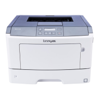
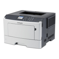
Print a Quick Test Page, and then check the top and bottom alignment indicators on the test page. The goal is
to make the skew at the top and bottom of the page parallel. Depending on the skew, turn the screw either
clockwise or counterclockwise using a 3‑mm hex wrench, and print a Quick Test Page to check the arrow
indicators on the top and bottom margins. Continue adjusting the screw as you check the results of each
adjustment on a new test page until you obtain the results you want. One full 360-degree turn of the aligner
adjustment screw changes the leading edge skew by roughly 1 mm (2 alignment indicator dots).
After the aligner roller adjustment is done, perform the polygon printhead mechanical registration adjustment.
See
“Polygon printhead mechanical registration adjustment” on page 405.
Polygon printhead mechanical registration adjustment
Perform the printhead mechanical registration adjustment procedure after you remove or replace the printhead,
or loosen the mounting screws.
Install the new printhead with the mounting screws lightly tightened before printing the Quick Test Page to see
if adjustment is needed.
4064
Parts removal
405
 Loading...