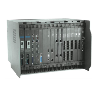
10 Matrix ETERNITY Quick Start
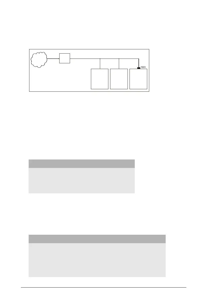
3. When the BRI port is configured in TE mode and connected as the last
terminal on the S0 bus (Multi-point configuration) as shown in figure 2.
Figure 2:
• Termination need not be inserted in case 2 and 3 above, if the S0 bus itself
supports Termination resistors.
• Termination need not be inserted if the BRI port of ETERNITY (configured in TE
mode) is connected as any terminal other than the last terminal on the S0 bus
(in a Multi-point configuration).
• To set the 100 termination on the BRI port set the Jumpers J3 and J4 located
on the BRI Module (daughter board) of the card as shown in the table.
Feeding Power to Terminal Equipment
• To feed power from ETERNITY to the terminal equipment connected to a BRI
port in the NT mode, change the position of the Jumpers J1 and J2 on the BRI
modules (daughter board) of the BRI Card as shown in the table.
Function Jumper Position
J3 J4
To insert 100termination (default position) AB AB
To remove 100termination BC BC
Function Jumper Position
J1 J2
To feed power on Tx and Rx wires (Phantom Power) AB AB
To feed power on separate pair of wires BC BC
No power to be fed to the terminal equipment (default position) Open Open
BRI TE
ETERNITY
BRI Line
BRI TEBRI TE
Other ISDN
Equipment
Other ISDN
 Loading...