M800S/M80/E80 Series Connection and Setup Manual
25 Setting the Position Switches
509
IB-1501269-J
25.2 Setting and Operation Examples of dog1 and dog2
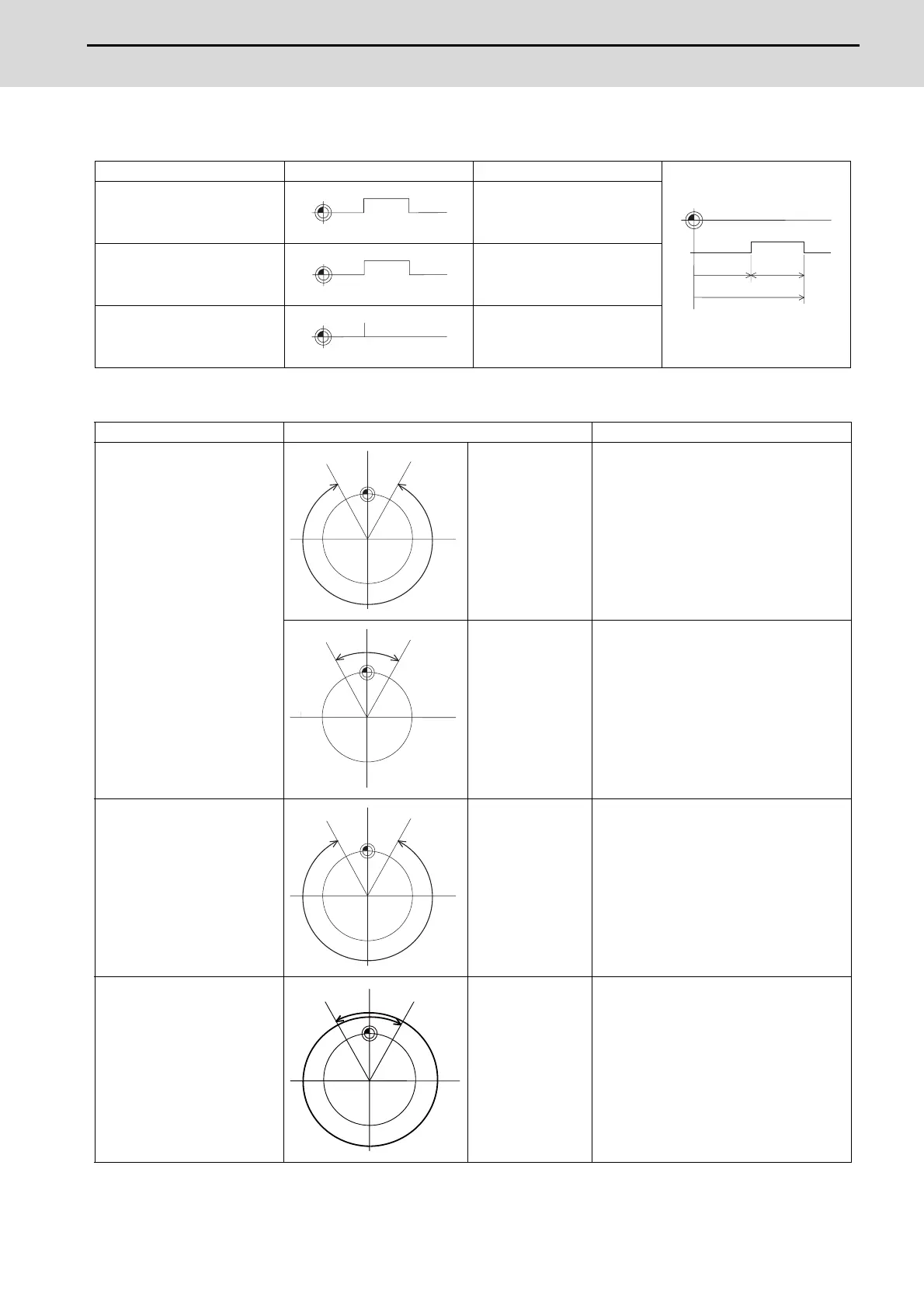
For rotary axes
Settings of dog1 and dog2 Positions of dog1 and dog2 Description
dog1 < dog2
A signal is output when the
machine reaches between
dog1 and dog2.
dog1 > dog2
A signal is output when the
machine reaches between
dog2 and dog1.
dog1 = dog2
A signal is output when the
machine is at dog1 (dog2).
Settings of dog1 and dog2 Positions of dog1 and dog2 Description
dog1 < dog2
(Example)
dog1 = 30.000
dog2 = 330.000
A signal is output when the machine
reaches between dog1 and dog2.
(Example)
dog1 = -30.000
dog2 = 30.000
Signal is output in the same manner even
if dog1 is in the negative area.
dog1 > dog2
(Example)
dog1 = 330.000
dog2 = 30.000
A signal is output when the machine
reaches between dog2 and dog1.
dog1 ≦ 0 and 360 ≦ dog2
(Example)
dog1 = -30.000
dog2 = 390.000
A signal is always output when the angle
of dog1 and dog2 is within a range of 0 to
360 degrees.
dog1
dog2
Basic machine coordinate
system zero point
Virtual
dog
PSW
range
dog2
dog1 = dog2
dog2 dog1
dog1 dog2
dog1 dog2

 Loading...


