Timer Interface Module A (TIMA)
Technical Data MC68HC908AB32 — Rev. 1.0
174 Timer Interface Module A (TIMA) MOTOROLA
11.5.2 Input Capture
With the input capture function, the TIMA can capture the time at which
an external event occurs. When an active edge occurs on the pin of an
input capture channel, the TIMA latches the contents of the TIMA
counter into the TIMA channel registers, TACHxH:TACHxL. The polarity
of the active edge is programmable. Input captures can generate
TIMA CPU interrupt requests.
$002B
Timer A Channel 1
Register Low
(TACH1L)
Read:
Bit 7 654321Bit 0
Write:
Reset: Indeterminate after reset
$002C
Timer A Channel 2 Status
and Control Register
(TASC2)
Read: CH2F
CH2IE MS2B MS2A ELS2B ELS2A TOV2 CH2MAX
Write: 0
Reset: 00000000
$002D
Timer A Channel 2
Register High
(TACH2H)
Read:
Bit 15 14 13 12 11 10 9 Bit 8
Write:
Reset: Indeterminate after reset
$002E
Timer A Channel 2
Register Low
(TACH2L)
Read:
Bit 7 654321Bit 0
Write:
Reset: Indeterminate after reset
$002F
Timer A Channel 3 Status
and Control Register
(TASC3)
Read: CH3F
CH3IE
0
MS3A ELS3B ELS3A TOV3 CH3MAX
Write: 0
Reset: 00000000
$0030
Timer A Channel 3
Register High
(TACH3H)
Read:
Bit 15 14 13 12 11 10 9 Bit 8
Write:
Reset: Indeterminate after reset
$0031
Timer A Channel 3
Register Low
(TACH3L)
Read:
Bit 7 654321Bit 0
Write:
Reset: Indeterminate after reset
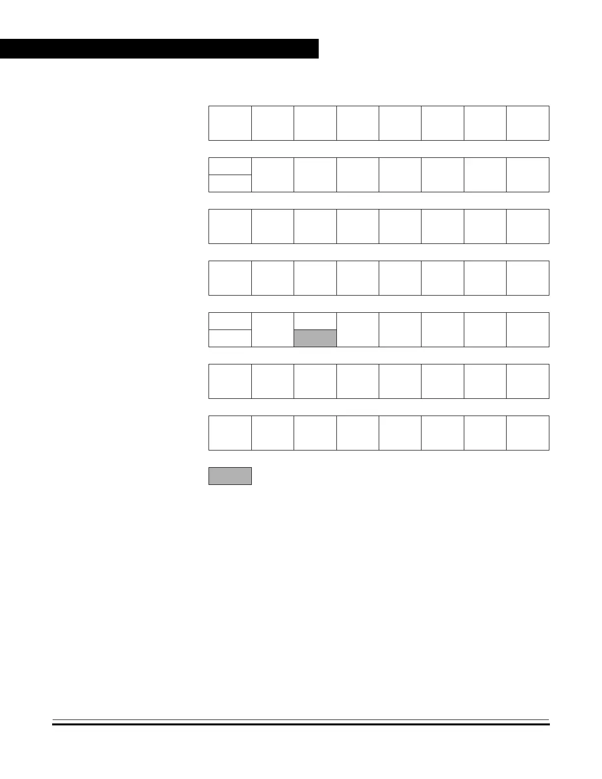
Addr. Register Name Bit 7 654321Bit 0
= Unimplemented
Figure 11-2. TIMA I/O Register Summary (Sheet 2 of 2)
 Loading...


