Serial Communications Interface
Technical Data MC68HC908AB32 — Rev. 1.0
252 Serial Communications Interface Module (SCI) MOTOROLA
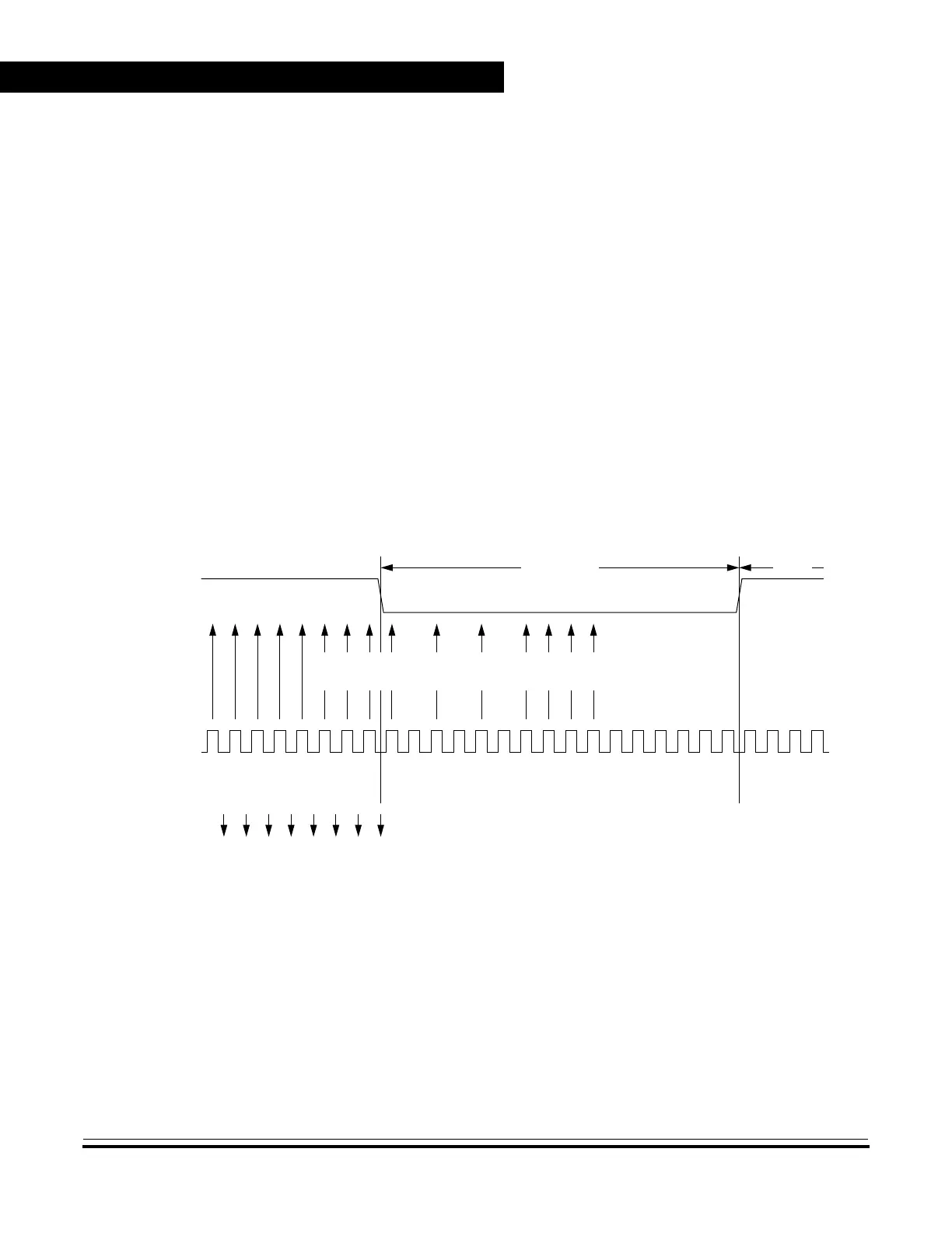
15.5.3.3 Data Sampling
The receiver samples the PTE1/RxD pin at the RT clock rate. The RT
clock is an internal signal with a frequency 16 times the baud rate. To
adjust for baud rate mismatch, the RT clock is resynchronized at the
following times (see Figure 15-6):
• After every start bit
• After the receiver detects a data bit change from logic 1 to logic 0
(after the majority of data bit samples at RT8, RT9, and RT10
returns a valid logic 1 and the majority of the next RT8, RT9, and
RT10 samples returns a valid logic 0)
To locate the start bit, data recovery logic does an asynchronous search
for a logic 0 preceded by three logic 1s. When the falling edge of a
possible start bit occurs, the RT clock begins to count to 16.
Figure 15-6. Receiver Data Sampling
RT CLOCK
RESET
RT1
RT1
RT1
RT1
RT1
RT1
RT1
RT1
RT1
RT2
RT3
RT4
RT5
RT8
RT7
RT6
RT11
RT10
RT9
RT15
RT14
RT13
RT12
RT16
RT1
RT2
RT3
RT4
START BIT
QUALIFICATION
START BIT
VERIFICATION
DATA
SAMPLING
SAMPLES
RT
CLOCK
RT CLOCK
STATE
START BIT LSB
PTE1/RxD
 Loading...


