COCKPIT SX
Page 12
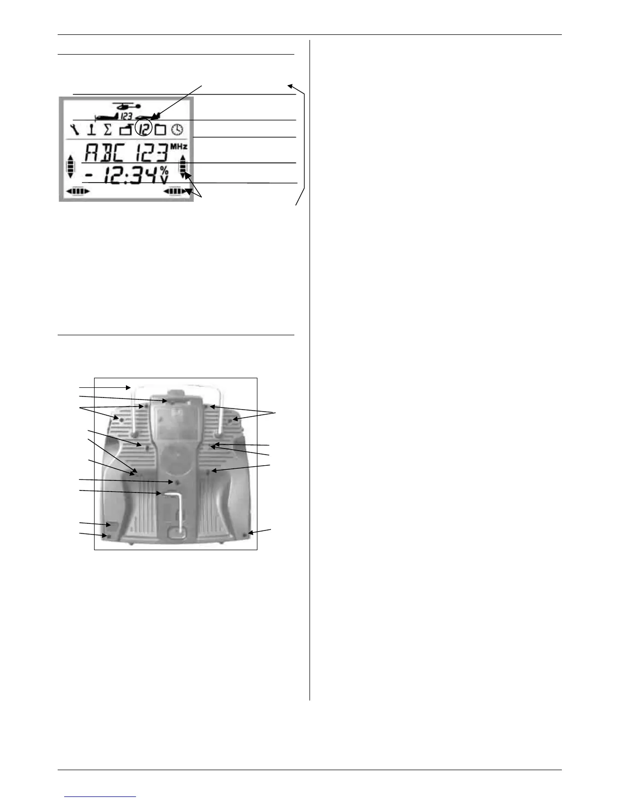
9.2. The screen
The picture below shows all the symbols and charac-
ters which can be displayed on the screen (never visi-
ble simultaneously).
The main menu symbol tells you whether the number in
the second line currently indicates the memory number
or the servo number.
K 3 = Servo 3 is selected
K 3 = Model memory 3 is selected
The symbols MHz, % and V indicate the meaning of
the number to their left.
9.3. The back of the transmitter
The case of the COCKPIT SX is screwed together, and
only needs to be opened if you need to replace the
battery, or adjust the stick centring spring tension.
Fig. 9.3: Back of transmitter
1. Carry handle
2. Sliding cover for the multi-function socket
(charge / discharge, Trainer mode, Diagnosis
mode, PC / simulator)
3. Adjustor screw for the right-hand stick unit
a. Disable stick centring (neutralising) spring
b. Set stick ratchet
c. Set stick friction brake
4. T6 TORX key for adjusting the sticks and open-
ing the transmitter case
5. Transmitter aerial release button
6. Adjustor screws for the left-hand stick unit
a. Disable stick centring (neutralising) spring
b. Set stick ratchet
c. Set stick friction brake
7. Case screws (7 x)
The tension of the stick centring springs is also variable
for each plane of stick movement. To adjust the set-
tings the transmitter must first be opened. (Î 9.4.)
9.3.1. Setting the ratchet for the
throttle / spoiler stick
There is no need to open the transmitter for this, as the
screws can be accessed through the holes in the back
of the transmitter. Fig. 9.3 shows the position of the
various adjustor screws.
Note: adjust the screws carefully!
Adjust the stick setting screws with care, and don’t
unscrew them too far if you wish to change your set-
tings for the centring springs, ratchet or friction, other-
wise the screws could press against the inside of the
back panel of the transmitter.
Disabling the centring spring:
Turn the screw 3 a. (right-hand stick) or 6 a. (left-hand
stick) clockwise until the stick no longer returns auto-
matically to centre from its end-points.
Activating the ratchet:
Turn the screw 3 b. (right-hand stick) or 6 b. (left-hand
stick) clockwise until the ratchet force feels right to you.
Activating the friction brake:
Turn the screw 3 c. (right-hand stick) or 6 c. (left-hand
stick) clockwise until the friction force feels right to you.
9.3.2. Changing the stick centring spring tension
The screws for altering the centring spring tension are
not externally accessible; the transmitter must be
opened for this (7 screws, i in Fig. 9.3.).
Note: open the transmitter carefully !
When opening the transmitter be careful to avoid the
battery falling out, as this could damage the connector,
the cable or the battery cells.
Fig. 9.4. shows which screw has to be adjusted for
each plane of stick movement.
Turning the screws has the following effect:
Turn clockwise =
greater centring spring tension
Turn anti-clockwise =
lower centring spring tension
Model type symbols
Flight phases 1, 2, 3
Main menu symbols
6 alpha-numeric characters
4 digits and “-” prefix
Memory No. Servo number
Trim settings
S
R
b.
R c.
R a.
S
M
N
S
O
a.
O b.
O
c.
S
P
Q
S

 Loading...