COCKPIT SX
Page 50
When you set up a new model, Throttle Check is al-
ways active (THRCHK = 1).
We recommend:
Don’t switch Throttle Check off unless you are sure that
it is not dangerous to switch the model on “with throttle”
(unpowered model, glow motor, speed controller with
power-on guard).
Moving to the TH CHK menu:
4 to MENU, r (SETUP appears),
r (MODEL appears), r (MODE appears),
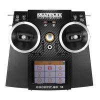
3 to TH CHK, r
“0” or “1” flashes in the bottom line.
THRCHK = “1”: active (default setting)
THRCHK = “0”: no Throttle Check
You can change the THRCHK setting using the 3-D
digi-adjustor.
A brief press r on the 3-D digi-adjustor concludes the
setting process. The selecting setting is now stored.
15.4. Adjusting servos
TIP: carry out mechanical adjustments first
It is always advisable to set up the mechanical systems
in the model as accurately as you can before carrying
out any (electronic) adjustments at the transmitter.
• Set the output arm on the servo output shaft at right-
angles to the case. This avoids inadvertently setting
up mechanical differential travel.
• Neutral point:
Set the desired neutral point of the control surfaces
as accurately as possible by altering the length of the
pushrods.
• Servo:
Connect the pushrod as far “inboard” as possible at
the servo output arm, and use the maximum avail-
able servo travel. This reduces the effect of gearbox
play, and exploits the servo’s power to the full.
• Control surface:
Connect the pushrod as far “outboard” as possible at
the horn. This reduces the effect of play in the link-
age, and transfers the servo’s power to the control
surface as efficiently as possible.
For each of the seven servos you can adjust the follow-
ing parameters:
- the centre
- the travel, separately in both directions
- the direction of rotation (REVerse)
These settings are used to adjust the control surface
travels and the neutral position to suit the requirements
of the model.
We recommend:
First check the direction of rotation, and correct this if
necessary (Î 14.4.1.).
Before you change the centre point (neutral position) of
the control surfaces at the transmitter, check and cor-
rect the control surface linkage mechanically at the
model. If the control surface settings are already close
to the neutral point, an offset to the servo centre of no
more than +/- 10% should be sufficient (Î 15.4.2.).
The final step is to adjust the servo travels (Î 15.4.3.).
15.4.1. Reversing the direction of servo rotation
Menu: (
SERVO) REV
Moving to the REV menu:
4 to MENU, r (SETUP appears),
3 to SERVO, r (SERVO1 appears),
43 select servo, r (CENTR appears),
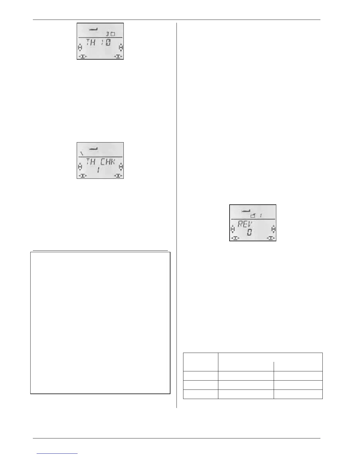
3 to REV r
“0” or “1” flashes in the bottom line.
REV = “0” : normal direction of rotation
REV = “1” : reversed direction
A brief press r on the 3-D digi-adjustor concludes the
process. The values are stored, and you can continue
with another servo.
Check (and correct if necessary) the direction of rota-
tion of the servos for all control functions.
Switching to another servo:
4 to EXIT, r (REV appears),
4 to EXIT, r (SERVO appears),
43 select servo r (CENTR appears),
3 to REV r (0 or 1 flashes)
The correct control response at the model:
Movement at the
Stick
Stick Control surface
RUDDER left left
ELEVATOR back (pull) up
AILERON left left aileron up

 Loading...