HK
for setting
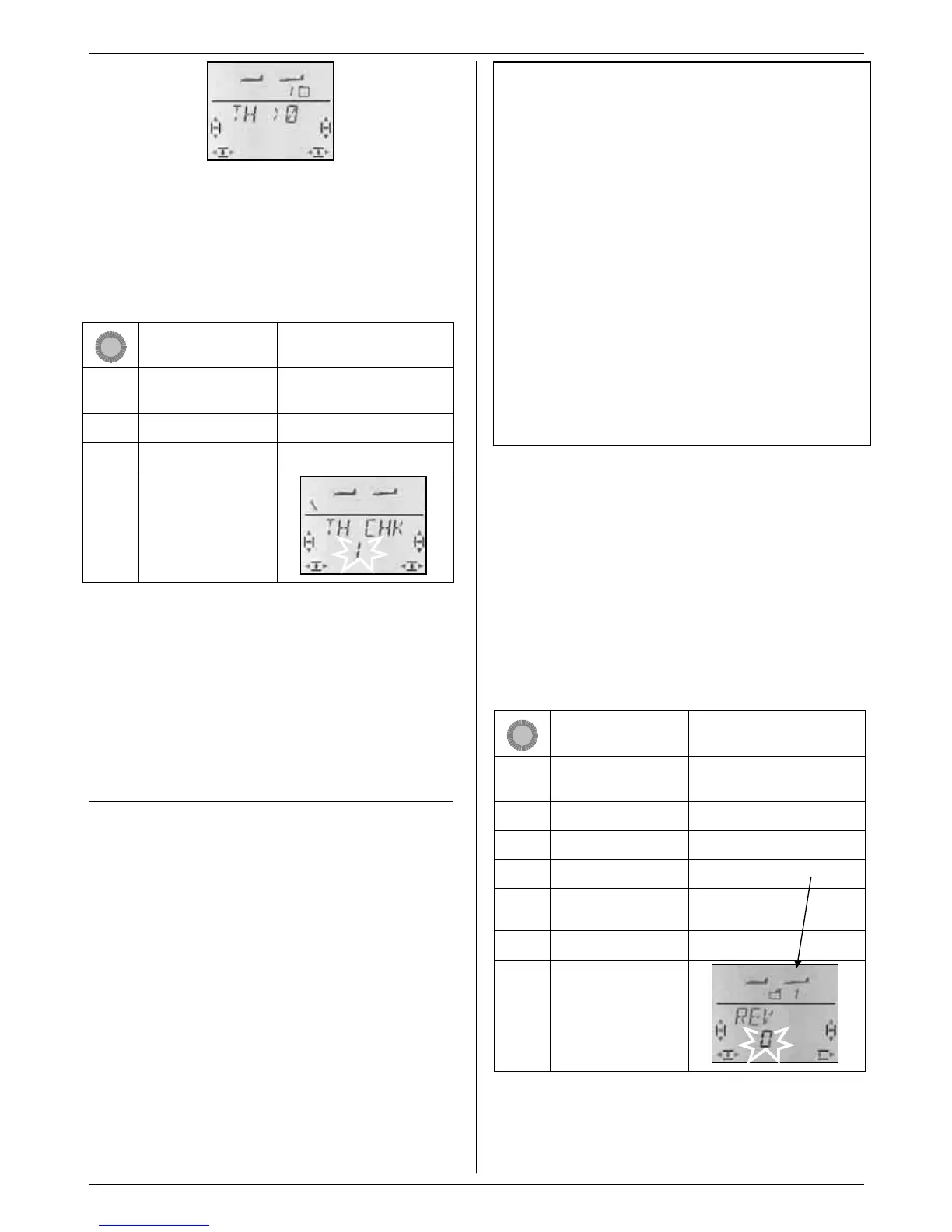
“0” or “1” flashes in the bottom line.
THRCHK = “1” means:
Throttle Check active (default setting)
THRCHK = “0” means:
No Throttle Check
You can change the THRCHK setting using the 3-D
digi-adjustor.
A brief press r on the 3-D digi-adjustor concludes the
process. The selected setting is now stored.
13.4. Adjusting servos
For each of the seven servos you can adjust the follow-
ing parameters:
- the centre
- the travel, separately in both directions
- the direction of rotation (REVerse)
These settings are used to adjust the control surface
travels and the neutral position to suit the requirements
of the model.
TIP: carry out mechanical adjustments first
It is always advisable to set up the mechanical systems
in the model as accurately as you can before carrying
out any (electronic) adjustments at the transmitter.
• Set the output arm on the servo output shaft at right-
angles to the case. This avoids inadvertently setting
up mechanical differential travel.
• Neutral point:
Set the desired neutral point of the control surfaces
as accurately as possible by altering the length of the
pushrod.
• Servo:
Connect the pushrod as far “inboard” as possible at
the servo output arm, and use the maximum avail-
able servo travel. This reduces the effect of gearbox
play, and exploits the servo’s power to the full.
• Control surface:
Connect the pushrod as far “outboard” as possible at
the horn. This reduces the effect of play in the link-
age, and transfers the servo’s power to the control
surface as efficiently as possible.
We recommend:
First check the direction of rotation, and correct this if
possible (Î 13.4.1.).
Before you change the centre point (neutral position) of
control surfaces at the transmitter, check and correct
the control surface linkage mechanically at the model.
If the control surface settings are already close to the
desired neutral point, an offset to the servo centre of no
more than +/- 10% should be sufficient (Î 13.4.2.).
The final step is to adjust the servo travels (Î 13.4.3.).
13.4.1. Reversing the direction of servo rotation
Menu: (
SERVO) REV
This is the procedure:
Action Effect
1. 4
r
Left to MENU
Confirm SETUP appears
3. 3
Right to SERVO
2. r
Confirm SERVO1 appears
3. 43
Select servo Servo number appears
4. r
Open selected servo
for setting
CENTR appears
3. 3
Right to REV
4. r
Open REV
for setting
“0” or “1” flashes in the bottom line.
REV = “0” means:
normal direction of rotation
REV = “1” means:
reversed direction of rotation
 Loading...