Key to the signal strength display:
no signal weak moderate strong very
measurable strong
You can now use the 3-D digi-adjustor to select a dif-
ferent frequency / channel; the screen will then display
the signal strength on that frequency.
b. Frequency / channel is free
The channel No. does not flash. A brief press r on the
3-D digi-adjustor confirms the selected setting for the
frequency / channel.
Your press is confirmed by a beep, and the blue LED
starts to flash. The transmitter is now ready to use.
The procedure now continues as described in Section
Î 10.2.3., unless the warning THR >0 appears on
the screen (throttle control not
in the idle / motor OFF
position.
10.3. Setting the frequency / channel
The procedure for setting the frequency / channel is
simple, fast and safe thanks to the transmitter’s integral
Synthesizer RF.
Simple, because the frequency and channel are
displayed on the screen.
Fast, because the 3-D digi-adjustor is used to select
the frequency / channel.
Safe, because the transmitter must be switched off and
then on again before a change of frequency /
channel takes effect. You also have to confirm
your chosen frequency with a brief press r on the
3-D digi-adjustor every time you switch on.
Note: no RF signal transmitted during frequency
setting
No RF signal is transmitted while you are selecting the
channel / frequency.
This is the procedure:
1. Hold the 3-D digi-adjustor pressed in
Switch the transmitter on
Release the 3-D digi-adjustor
The screen now displays the current frequency,
with the associated channel number flashing.
The blue LED glows constantly.
2. Selecting the channel
You can now use the 3-D digi-adjustor to
search for the channel you wish to use. The
screen also displays the associated frequency.
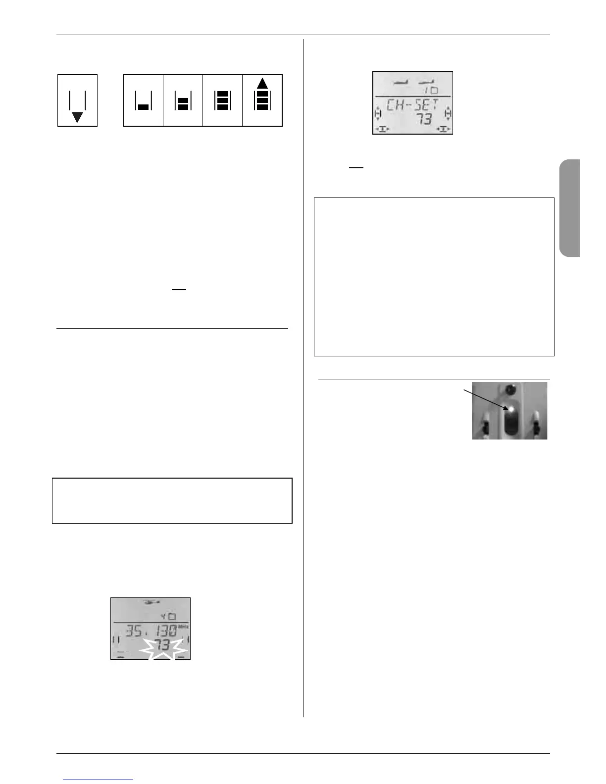
3. Confirming the channel
A brief press r on the 3-D digi-adjustor con-
firms your choice, and this display appears:
4. Activating the frequency / channel
Switch the transmitter off, then on again.
(do not
press the 3-D digi-adjustor).
The procedure now continues as described in the
previous section 10.2.
Notes:
Check with other pilots !
(frequency control, channel clashes)
Check with the other pilots at the site which fre-
quencies / channels they are using. Do this before
you change to a new frequency / channel.
Select approved frequencies / channels only !
The permissible frequencies / channels vary from
country to country. Select only those frequencies /
channels which are approved for use where you
are operating your equipment.
Please refer to the sheet entitled “R&TTE” in the
transmitter documentation.
10.4. The RF status indicator (blue LED)
The blue LED (light-emitting diode)
indicates the status of the RF
module. It only lights up when the
transmitter is switched on.
LED flashing Î RF signal being transmitted
The LED flashes briefly at intervals of around 1 second
to indicate that the transmitter is ready for use, and is
transmitting an RF signal.
LED glowing constantly Î No RF signal
If no RF signal is being transmitted, the cause may be
any of the following:
• Frequency / channel not yet confirmed after the
transmitter has been switched on Î 10.2.
• Plug present in the multi-function socket;
this switches the RF section off
(Diagnosis lead, Pupil lead on Trainer cable, PC
simulator interface)
• Transmitter deliberately running without an RF signal
(long press ª on the 3-D digi-adjustor after switching
on) Î 10.2.2.
• Technical fault in the RF section

 Loading...