Note: making the EXP effect visible on the model
EXP does not affect the centre point or end-points of
the control surfaces. If you wish to see the effect of
your settings on the model, you must hold the stick at
half-travel.
A brief press r on the 3-D digi-adjustor concludes the
process. The value is now stored.
If you turn the 3-D digi-adjustor to the left, you can
leave this menu via “EXIT”. Turning it to the right takes
you to the EXP settings for ELEVATOR and RUDDER.
AILERON (AI)
EXP AI
ELEVATOR (EL)
EXP EL
RUDDER (RU)
EXP RU
The EXP values for ELEVATOR and RUDDER are set
using the method described above for EXP A.
13.7. More features which can be ex-
ploited with the EASY model type
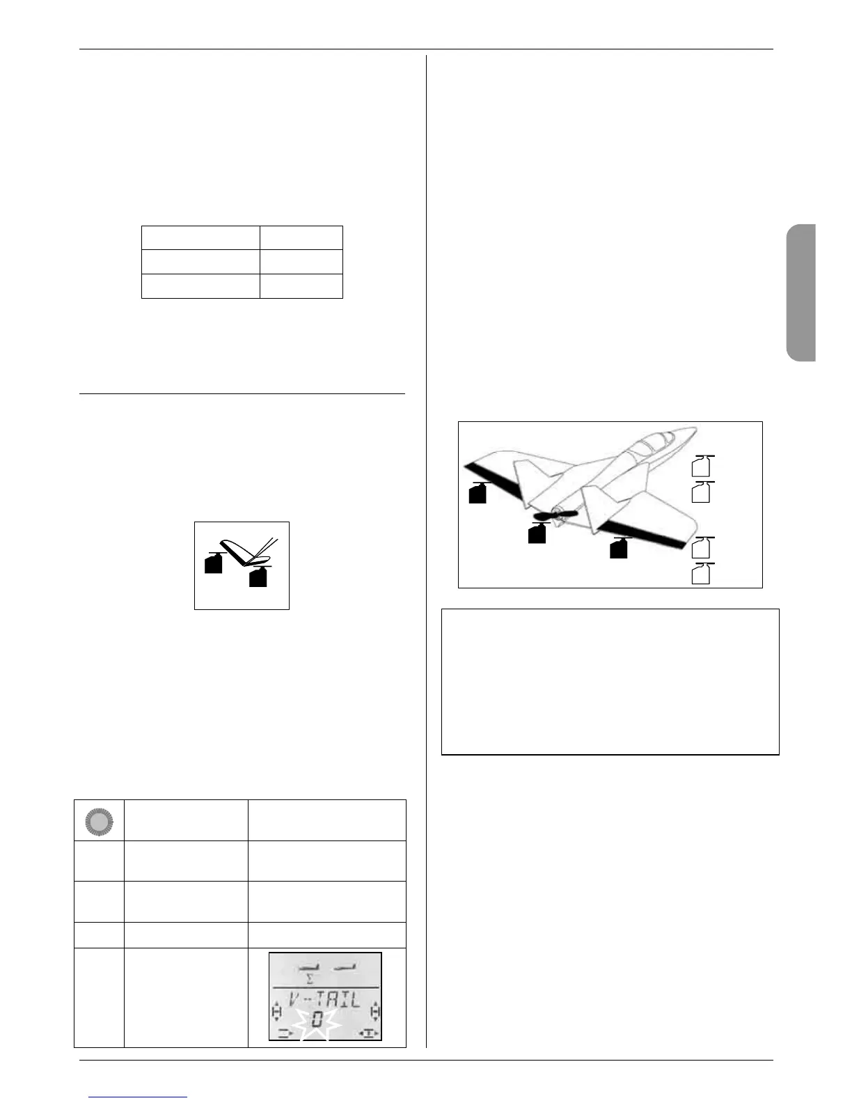
13.7.1. Controlling V-tail models
Menu: (
MIXER) V-TAIL
At this point you can activate the pre-defined mixer for
a model with a V-tail.
The two servos for the V-tail must be connected to
receiver outputs 2 and 3.
2
3
The V-tail mixer can be assigned in any of eight differ-
ent ways: 1 to 4 and -1 to -4. This is necessary be-
cause the servos and control surface horns can be
installed in many different arrangements.
This makes it easier than ever before to set up a V-tail,
as it eliminates the need to reverse servos or swap
servo connections at the receiver.
Set “0” if your model has a cruciform (cross-) tail or a T-
tail.
The procedure for activating the V-LEIT mixer:
Action Effect
1. 4
r
Left to MENU
Confirm SETUP appears
2. 3
r
Right to MIXER
Confirm GAS>S4 appears
2. 3
Right to V-LEIT
3. r
Open V-LEIT
for setting
The current setting for the V-TAIL mixer flashes in the
bottom line of the screen.
Now proceed as follows:
a. Pull the ELEVATOR stick back, and hold it there.
b. Change the V-tail mixer mode from 1 to 4 using
the 3-D digi-adjustor until both control surfaces are
at the correct setting (up).
c. Move the RUDDER stick to the left and hold it
there.
d. If the control surfaces now operate in the wrong
direction, use the 3-D digi-adjustor to set the same
mode (1 to 4), but with “-” as prefix.
A brief press (r) on the 3-D digi-adjustor concludes the
process, and the value is stored.
13.7.2. Deltas and flying wings
Menu: DELTA
Deltas and flying-wing models require a mixer which
superimposes the functions AILERON and ELEVA-
TOR, and passes the mixed travels to the two control
surfaces (servos 1 and 2).
PH
AUX 2
2
1
4
3
5
6
7
SPOILER/
THR-LIMIT
Delta
left
Delta
right
Throttle
Rudder
Elevator
Caution: servos 1 and 2 are used
The servo assignment differs from the “usual” ar-
rangement for the EASY model type. If you activate
DELTA (value other than 0%), you must use receiver
outputs 1 and 2 for controlling the servos.
This arrangement makes it possible to use small, light-
weight four-channel receivers in deltas / flying wings.
The ELEVATOR signal is now present at receiver out-
put 5 instead of AILERON.
The magnitude of the AILERON travels is adjusted in
the MIXER menu under A -> A (Î 13.8.2.). Changes
made here affect both control surfaces equally.

 Loading...