14.10.4. Copying flight phases
Menu: (
PHASES) COPY
What is copied?
• The current trim settings for AILERON, ELEVATOR
and RUDDER
• Flight phase-specific mixer inputs
Q ->Q aileron input to the outboard flaps
Q ->F aileron input to the inboard flaps
FIX F fixed value for FLAP Î 14.11.2.
mixer inputs for the free mixers Î 14.12.
• Flight phase-specific transmitter control settings
Dual-Rate for AILERON, ELEVATOR and
RUDDER Î 14.9.1.
Fixed values for AILERON, ELEVATOR, RUDDER,
which are called up using the FIX button Î 14.11.5.
The source is always the current flight phase, which
you have selected with the PH switch.
The destination for the copy is selected in the menu.
Moving to the KOPIE menu:
4 to MENU, r (SETUP appears),
r (MODEL appears), r (MODE appears),
3 to PHASEN, r,
3 to KOPIE, r
The number 0 flashes in the bottom line. Select phase
1 to 3 as destination using the 3-D digi-adjustor.
Check once more that you have selected the correct
source with the PH switch (Î table in section 14.4.3.).
A further brief press r on the 3-D digi-adjustor triggers
the copy process, and the flashing ceases.
Note: interrupting without making a copy
If you leave 0 as the destination, no copy will be made.
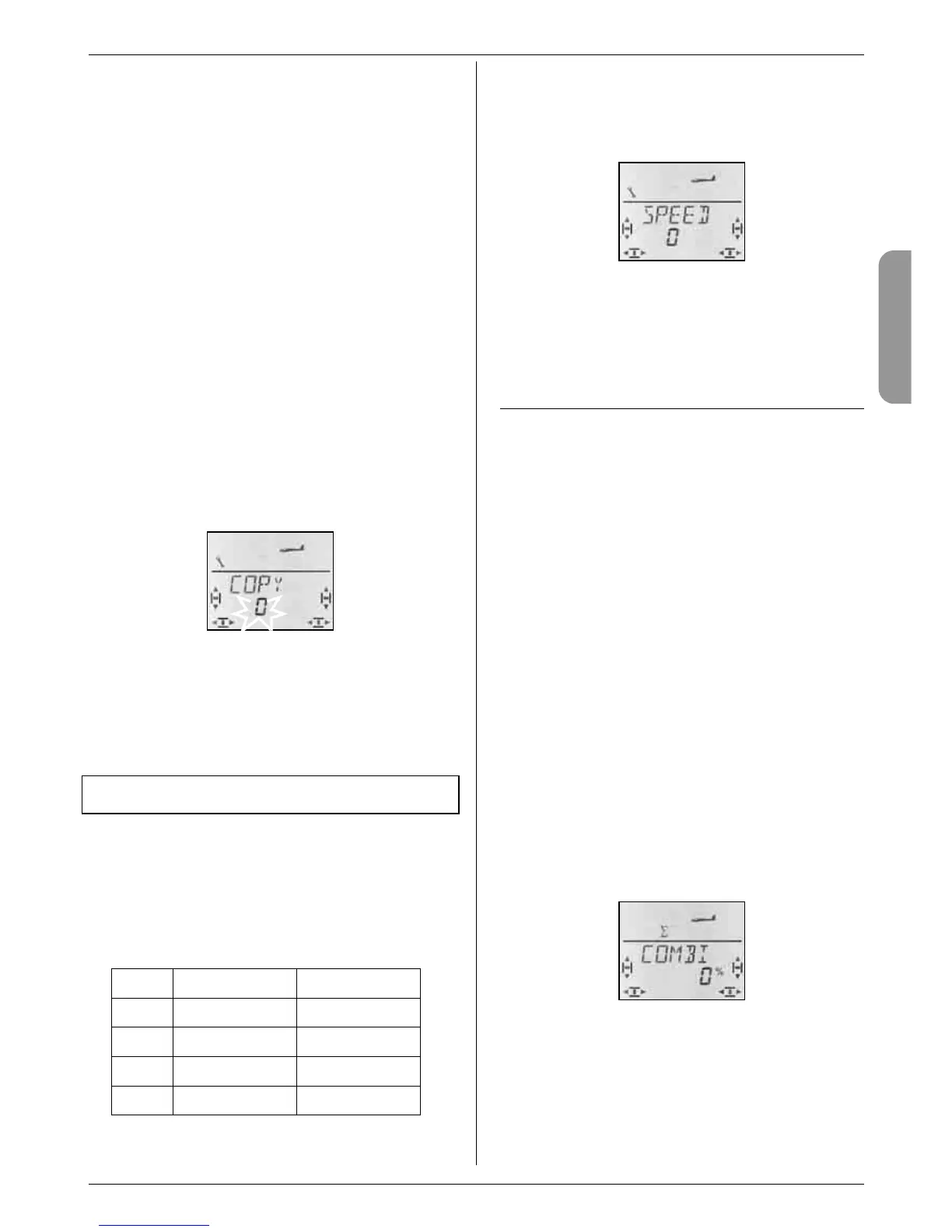
14.10.5. Setting the transition speed for switching
flight phases
Menu: (
PHASES) SPEED
The SPEED parameter can be adjusted to determine
the speed of the transition from one flight phase to
another.
Four settings are possible:
SPEED
Transition
0
immediate
1
fast approx. 1 sec
2
moderate approx. 2 sec
3
slow approx. 3 sec
Moving to the SPEED menu:
4 to MENU, r (SETUP appears),
r (MODEL appears), r (MODE appears),
3 to PHASEN, r,
3 to SPEED, r
The current setting flashes. Select the desired value
using the 3-D digi-adjustor.
A brief press r on the 3-D digi-adjustor concludes the
process. The value is stored.
14.11. Further possible functions with the
GLIDER model type
14.11.1. Combi-Switch
Just like their full-size counterparts, many models -
especially gliders - are only able to fly smooth turns
with co-ordinated use of ailerons and rudder. The
combi-switch combines (couples) ailerons and rudder,
making it easier for modellers to fly accurate turns in
normal flight. For thermal flying and aerobatics the
combi-switch is not generally used.
The combi-switch mixer itself can be switched on and
off at any time using the “CS/A-ROT” switch (switch
position ON).
You can set the following rate in the COMBI menu. The
available range is -200% to 200% in 5% increments.
The prefix determines the direction of following. In most
cases the model’s rudder deflects when the aileron
stick is operated, i.e. the aileron function is the “mas-
ter”. To achieve this the values must be set with a posi-
tive prefix (+). A following rate of 100% means that full
aileron deflection produces full rudder deflection. A
following rate of 200% means that full rudder deflection
is obtained when the aileron stick is only at half-travel.
Moving to the COMBI menu:
4 to MENU, r (SETUP appears),
3 to MIXER, r (GAS>S4 appears, e.g.),
3 to COMBI, r
The current percentage figure flashes. You can now set
the value within the range -200% to +200% using the
3-D digi-adjustor.
A brief press r on the 3-D digi-adjustor concludes the
process. The value is stored.
 Loading...