15. Setting up a new model
Model type: ACRO
15.1. What is ACRO ?
ACRO is the model type for power models, hot-line
electric models and similar aircraft.
The ACRO model type is represented on-screen by the
following symbol:
What is possible with the ACRO type:
• setting up differential aileron travel
• raising both ailerons as a landing aid
• snap-flap (elevator / aileron mixer)
• pitch trim compensation for spoiler and motor
(elevator compensation)
• controlling V-tail models
• using three flight phases
(e.g. aerobatics / normal / landing)
• using three free mixers
• setting up fixed values for AILERON / ELEVATOR /
RUDDER, calling them up using FIX
(automatic aerobatics)
• switching the motor off quickly using emergency
throttle off (Throttle Cut)
This is the general procedure:
The following procedure is divided up as follows: in the
first six steps you set up a power model “without any
extras”. How you proceed thereafter depends on the
features of your particular model (four wing flaps, V-tail,
power system), and which of the programming facilities
of the C
OCKPIT SX you wish to use (flight phases,
automatic aerobatics, etc.).
• Connect the servos in the model to the receiver
Î 15.2.
• Prepare the transmitter for the model
Î 15.3.
• Set up the servos (direction, centre, travels)
Î 15.4.
• Set up the aileron mixers
Î 15.5.
• Set up the elevator mixers (with
compensation for throttle / spoiler / flaps) Î 15.6.
If your model has a V-tail:
• Activate and set up the V-tail Î 15.7.
If you wish to use flight phases:
• Activate flight phases Î 15.9.
Further options:
• Combi-Switch Î 15.10.1.
• Electronic Y-lead
(e.g. using servos 6 + 7 for landing flaps) Î 15.10.4.
• Fixed values for aileron / elevator / rudder)
(automatic aerobatics) Î 15.10.2.
• Using free mixers Î 17.
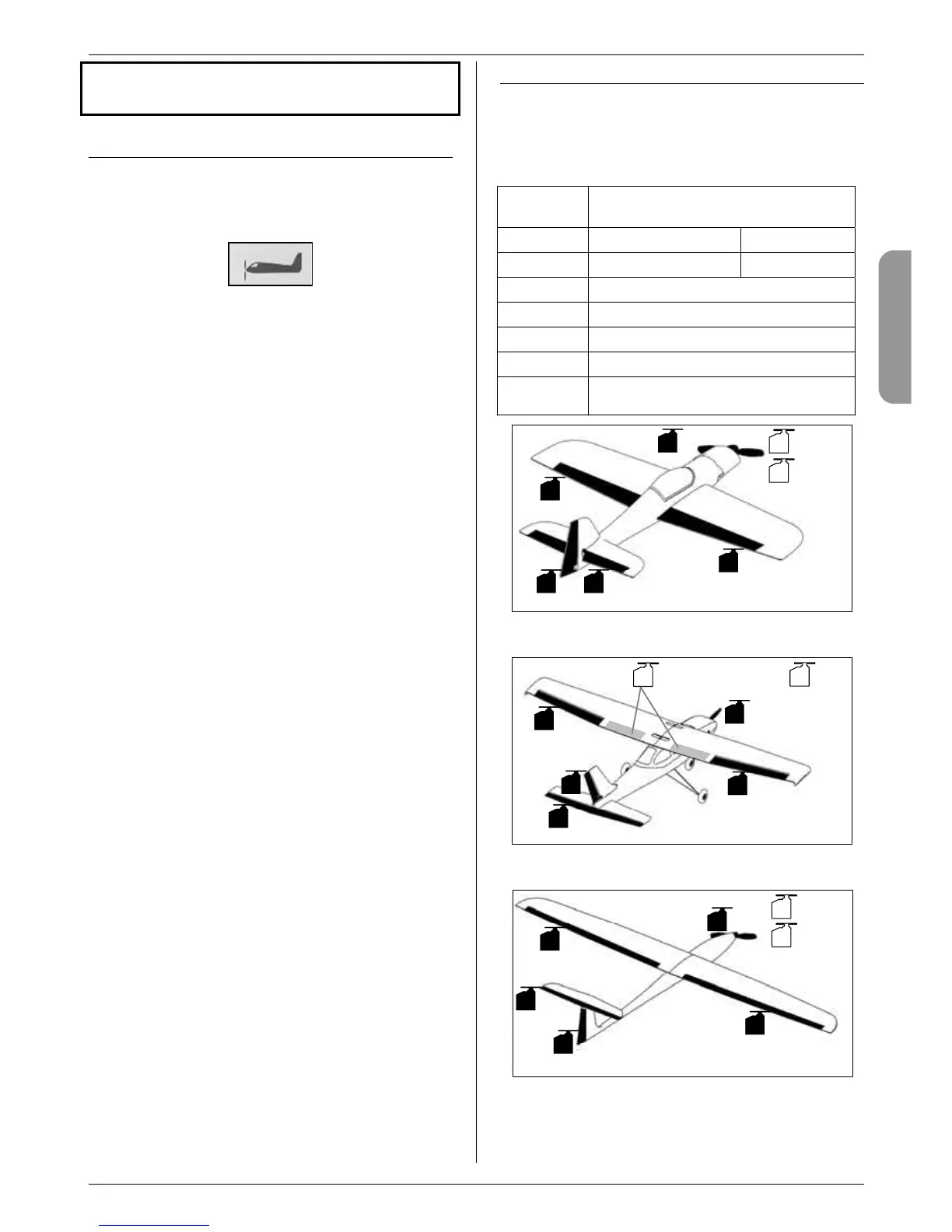
15.2. Preparing the model
Connect the servos in the model to the receiver in the
sequence stated in the table below.
The C
OCKPIT SX can only operate your model correctly
if the servos are connected to the receiver in the cor-
rect sequence.
Receiver
output
Function
1
Aileron 1 Delta 1
2
Elevator (or V-tail 1) Delta 2
3
Rudder (or V-tail 2)
4
Throttle
5
Aileron 2
6
SPOILER
7
AUX 2
(or other assignment with Y-lead Î 15.10.4.)
1
5
4
3
2
6
7
PH
AUX 2
SPOILER/
THR-LIMIT
Elevator
Aileron left
Aileron right
Throttle
Rudder
Aerobatic model
SPOILER/
THR-LIMIT
6
7
PH
AUX 2
1
5
4
3
2
Elevator
Aileron left
Aileron right
Throttle
Rudder
Power trainer
SPOILER/
THR-LIMIT
6
7
PH
AUX 2
5
1
3
2
4
Aileron left
Throttle
Aileron right
Elevator
Rudder
Hot-line model, ...
 Loading...