12
5.2) Description of functions
Here is a brief description of the functions that can be added by set-
tingthecorrespondingDip-Switchto“ON”.
Switch 1-2: OffOff =“Manual”movement(handoperated)
On-Off =“Semiautomatic”movement
Off-On =“Automatic”movement(automaticclosing)
On-On =“Automatic+AlwaysClose”movement
Inthe“Manual”operatingmode,thegatewillonlymoveaslongas
the control button is held down.
In “Semiautomatic”mode, a command impulse will perform the
whole movement until the Working Time limit expires or the limit stop
isreached.Inthe“Automatic”operatingmode,anopeningmanoeu-
vre is followed by a pause, after which the gate closes automatically.
The “Always Close” function comes into play following a power
failure, automatically activating a closing manoeuvre preceded by 5
secondsofpre-ashing.
Switch 3: On = Condominium operation (not available in Manual
mode)
In the Condominium operating mode, once an opening manoeuvre
has started it cannot be interrupted by other command impulses,
suchasSTEP-BY-STEPorOPEN,untilthegatehasnishedopen-
ing. During a closing manoeuvre, a new command impulse will stop
the gate and reverse the direction of movement in order to open
the gate.
Switch 4:On=Pre-ashing
Acommandimpulseactivatestheashinglight,followedbymove-
ment5secondslater(2secondslaterinmanualmode).
Switch 5:On=Close5”afterPhoto<inautomaticmode>orClose
after Photo < in semiautomatic mode >
This function, in Automatic mode, allows the gate to be kept open
only for the time required for transit; when the PHOTO stage is over,
the manoeuvre stops. After 5 seconds a closing manoeuvre will
automaticallybegin.IfPHOTOtriggersinthe“Semiautomatic”mode
duringaclosingmanoeuvre,the“Automatic”closingmanoeuvreis
activated with a set pause time.
Switch 6:On=Safety(Photo1)alsoduringtheopeningmanoeuvre
The“Photo1”safetydeviceisnormallyactiveonlyduringtheclos-
ingmanoeuvre;ifDip-Switch6isturned“On”,thesafetydevicewill
cause the movement to stop also during the opening manoeuvre.
In the Semiautomatic or Automatic modes, the opening manoeuvre
will start again immediately after the photocell has been disengaged.
Switch 7: On = Ramming
When reversible actuators are used, so that the gate does not
remain closed thanks to the thrust of the motors alone, it is neces-
sarytoinstallanelectriclock(seeactuators’operatinginstructions).
The electric lock may apply a natural thrust to the gate, causing the
leaves to open slightly; at times this thrust is so powerful as to cause
the locking mechanism to jam.
With the ramming function on, a brief closing cycle is activated
before an opening manoeuvre is started. This, however, will not
generate any actual movement since the leaves will already be posi-
tioned against the closing limit stop.
This way, when the electric lock is activated it will be free from the
effects of unwanted forces and will readily click open.
Switch 8: On = Deceleration
Deceleration consists in a 30% reduction of the nominal speed, to
reduce the impact force in the gate opening and closing zones.
The deceleration function slows down the automation speed and
reduces motor torque by 70%.
In automations requiring a high torque, this torque reduction could
cause shutdown of the motors.
For this reason, this function is disabled on heavyweight gates and
those subject to high friction.
Oncethedecelerationfunctionisenabled,theWorkTime(WT)trim-
mer must be adjusted as the deceleration start depends on the set
Work Time. Therefore set the Work Time so that deceleration starts
at approx. 50 cm before the mechanical stops to ensure that the
manoeuvre lasts a further 3-5 seconds after reaching the mechani-
cal stop.
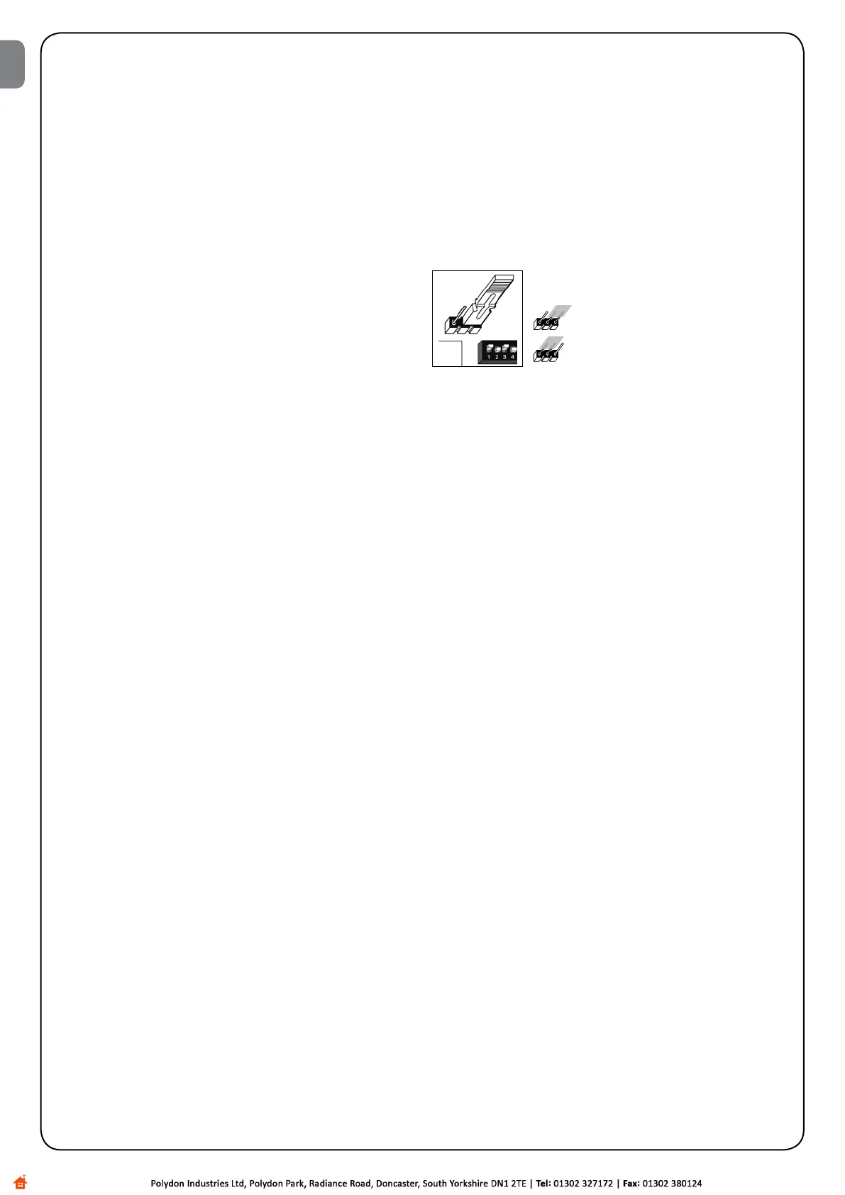
Ajumper(M-RAL)isttedonthecontrolunittoenableselection
of the two DECELERATION modes; one with 70% torque reduction
and one with 60% torque reduction to use on heavier gates.
70% torque reduction
60% torque reduction
Note that during deceleration, the motor noise levels increase slightly.
Before adjusting deceleration settings, read paragraph “4 Adjust-
ments”withspecialreferencetotheoperationoftheBalancetrim-
mer(BAL).
Switch 9: On = Maintain pressure
With hydraulic actuators, the thrust required to keep the gate closed
is generated by a hydraulic circuit which is constantly under pres-
sure.
However, time and wear tend to reduce the seal of the hydraulic
circuit. Consequently, after a few hours of operation the internal
pressure may drop, causing the leaves to open slightly.
Ifthe“MaintainPressure”functionisenabled,every4hoursthatthe
gate remains closed a brief closing manoeuvre is activated in order
to restore the hydraulic circuit pressure.
Switch 10: On = Phototest
This function checks photocell efciency at the beginning of each
manoeuvre. See the PHOTOTEST chapter.
Switch 11: On = Courtesy light in impulse mode
In this mode, the clean contact of the courtesy light output will
remain closed for 1 sec. at the starting of each opening or closing
manoeuvre, thus enabling a command impulse to be sent to an
external timer.
Switch 12: On = CLOSE becomes OPEN for Pedestrians
In this mode, the CLOSE input loses it basic function and becomes
a Pedestrian Step-by-Step input that allows the gate leaf controlled
by motor 2 to be opened for pedestrian access.
The Pedestrian opening cycle can only be activated when the gate
is closed, while if the gate is moving or open the impulse has no
effect on the input.
EN

 Loading...


