8
For the most part, connections are easy; a lot of them are direct connections to a single user point or contact but some are a little more
complex:
All the single-phase asynchronous motors need a capacitor for them to work properly; some gearmotors have this capacitor already con-
nected inside while others have to have the capacitor connected externally. In this case, the capacitor must be connected between the
motor’s OPEN and CLOSE phases. To be more practical the capacitor should be connected directly inside the unit.
The“Phototest”functionimprovesthereliabilityofthesafetydevices
and puts the control unit and safety photocells in “category 2”
accordingtoEN954-1standard(ed.12/1996).
Each time a manoeuvre is begun, the related safety devices are
checked and the manoeuvre is started only if everything is in order.
Should the test be unsuccessful (the photocell is blinded by the
sun,cableshaveshortcircuited,etc.)thefailureisidentiedandthe
manoeuvre is not carried out.
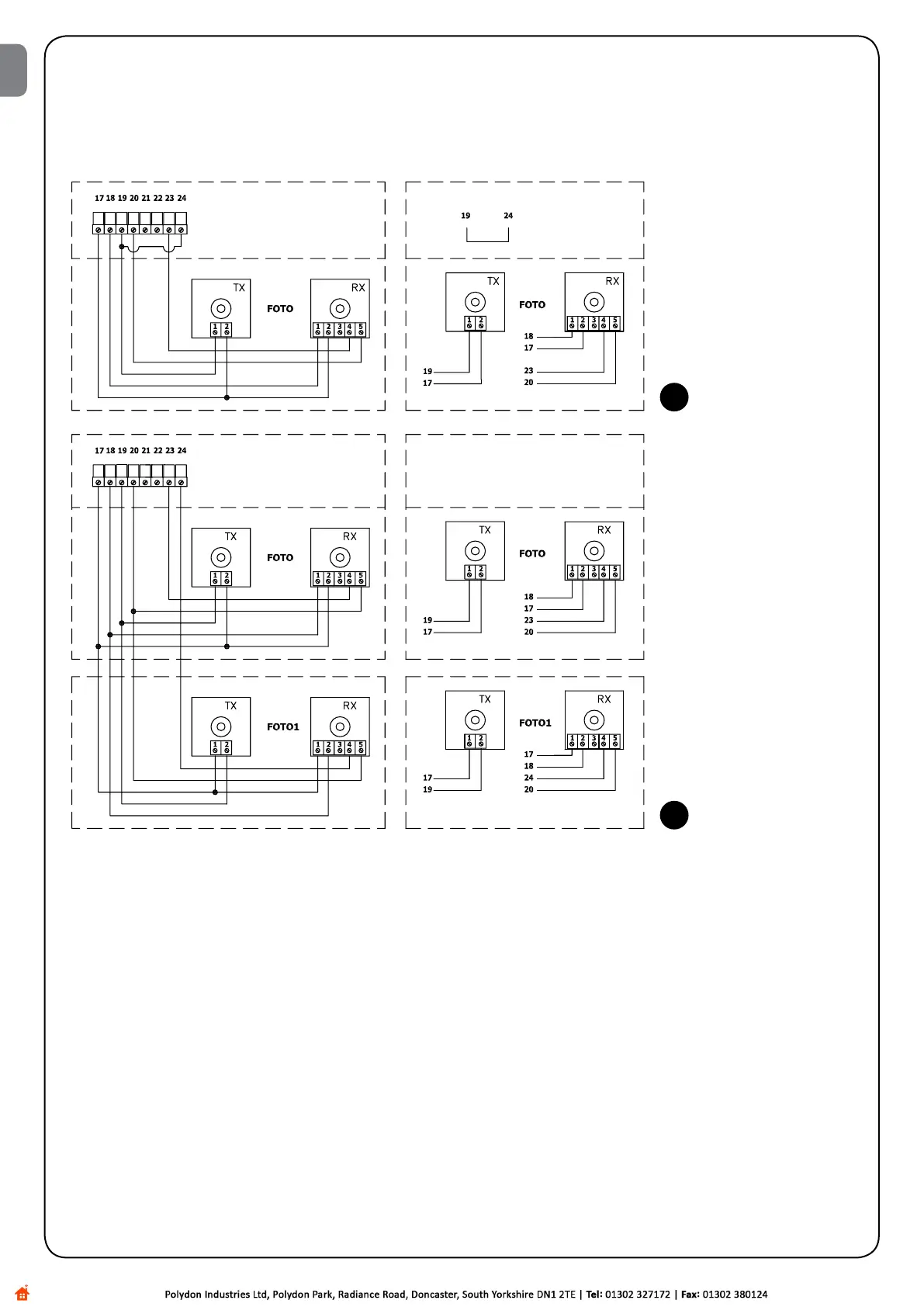
To enable the Phototest function:
•SetDipSwitch10toON
•Connect the safety devices as shown in (when using the
PHOTOoutputalone),orasshownin(whenusingPHO-
TO1aswell).
The photocell transmitters are not powered directly from the ser-
vice output, but through the dedicated PHOTOTEST output. The
maximumcurrentavailableatthePHOTOTESToutputis75mA(3
pairsofphotocells).
•Powerthereceiversdirectlyfromtheserviceoutputofthecontrol
unit(terminals17-18).
The photocells are tested as follows: when a movement is required,
all the receivers involved in the movement are checked to make sure
they give their consent, then power to the transmitters is discon-
nected; next all the receivers are checked to make sure they signal
the fact by withholding their consent; the transmitters are then
poweredandtheconsentofallthereceiversisveriedoncemore.
Only if this sequence is successfully carried out will the manoeuvre
be performed.
It is always a good idea to activate the synchronisation function by
cutting the jumpers on the transmitters. This is the only way to make
sure that two pairs of photocells will not interfere with each other.
Readtheinstructionsfor“SYNCHRONISED”operationinthepho-
tocell manual.
IfaninputsubjectedtoPHOTOTESTisnotbeingused(seePHO-
TO1)butyoustillrequirethephototestfunction,connecttheunused
inputwiththePHOTOTESToutput(terminals19-24)usingajumper;
see .
If at a later time the Phototest function is no longer required, set Dip-
Switch 10 to the OFF position.
5
5a
EN
 Loading...


